Quick answer: To convert inches to mm, multiply the inch value by 25.4. The factor is exact: 1 in = 25.4 mm. Example: 3 in × 25.4 = 76.2 mm. For a toleranced drawing, convert the lower and upper limits too; don’t convert only the nominal size.
An inches to mm calculation is easy. Deciding what the converted number means on a drawing, inspection report, or request for quotation takes more care. An exact arithmetic result can still be shown with the wrong precision, and a nearby metric stock size may be a different part rather than an equivalent one.
TL;DR
- Multiply inches by exactly 25.4 to obtain millimetres.
- Keep extra digits during the calculation; choose display precision after considering the source measurement and the application.
- For toleranced dimensions, convert the minimum and maximum limits independently.
- Soft metric conversion describes the same physical size. Hard metric substitution may select a different standard size.
- On a supplier handoff, state which unit controls acceptance and label translated values as reference-only unless the drawing owner approves otherwise.
Instant
mm
1 in = 25.4 mm
1 in = 25.4 mm exactly. Results are calculated before display rounding; keep the controlling drawing unit and tolerance.
How to Convert Inches to MM
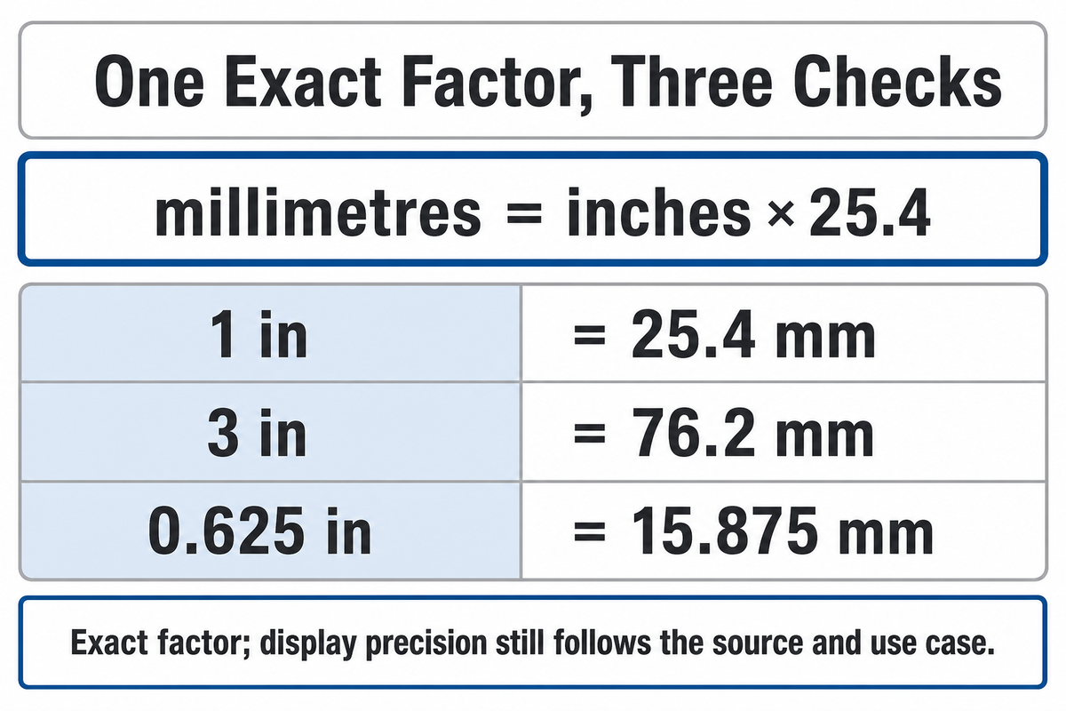
The core conversion has one operation: multiply the inch value by 25.4. The result is in millimetres because the inch unit cancels against the denominator in 25.4 mm per inch. This factor is exact, so any uncertainty comes from the input measurement, later rounding, or the physical specification, not from 25.4 itself.
An inch is a unit of length used in the United States customary system and retained in many drawings, tools, and components in Canada and the United Kingdom. The millimeter—spelled millimetre in international English—belongs to the metric system and uses the symbol mm. An inch to millimeter calculation connects these systems of measurement; it does not change the physical item being described.
For everyday length conversions, a calculator can produce the number. For production, also identify the source of the input. A tape-measure reading of 3 in, a drawing callout of 3.000 in, and a limit of 3.000 ±0.005 in all multiply by the same factor, but they shouldn’t automatically be reported with the same number of digits.
millimetres = inches × 25.4
- Write the value in decimal inches. A whole number, such as 3 in, is already ready.
- Multiply by 25.4 mm/in.
- Keep the unrounded result while you calculate.
- Display only the precision justified by the source value and use case.
For example, 3 in × 25.4 mm/in = 76.2 mm. A 5 in dimension becomes 127 mm, 10 in becomes 254 mm, and 12 in becomes 304.8 mm. The same method works for decimals: 0.625 in × 25.4 = 15.875 mm.
“The value for the inch is exactly equivalent to 25.4 mm.”
Evidence capsule: NIST identifies 1 in as exactly 25.4 mm and records July 1, 1959 as the effective date of the international definition. “Exact” describes the factor; it doesn’t mean a measured 3.0 in input suddenly has unlimited precision after multiplication.
Inches to MM Chart for Common Fractions
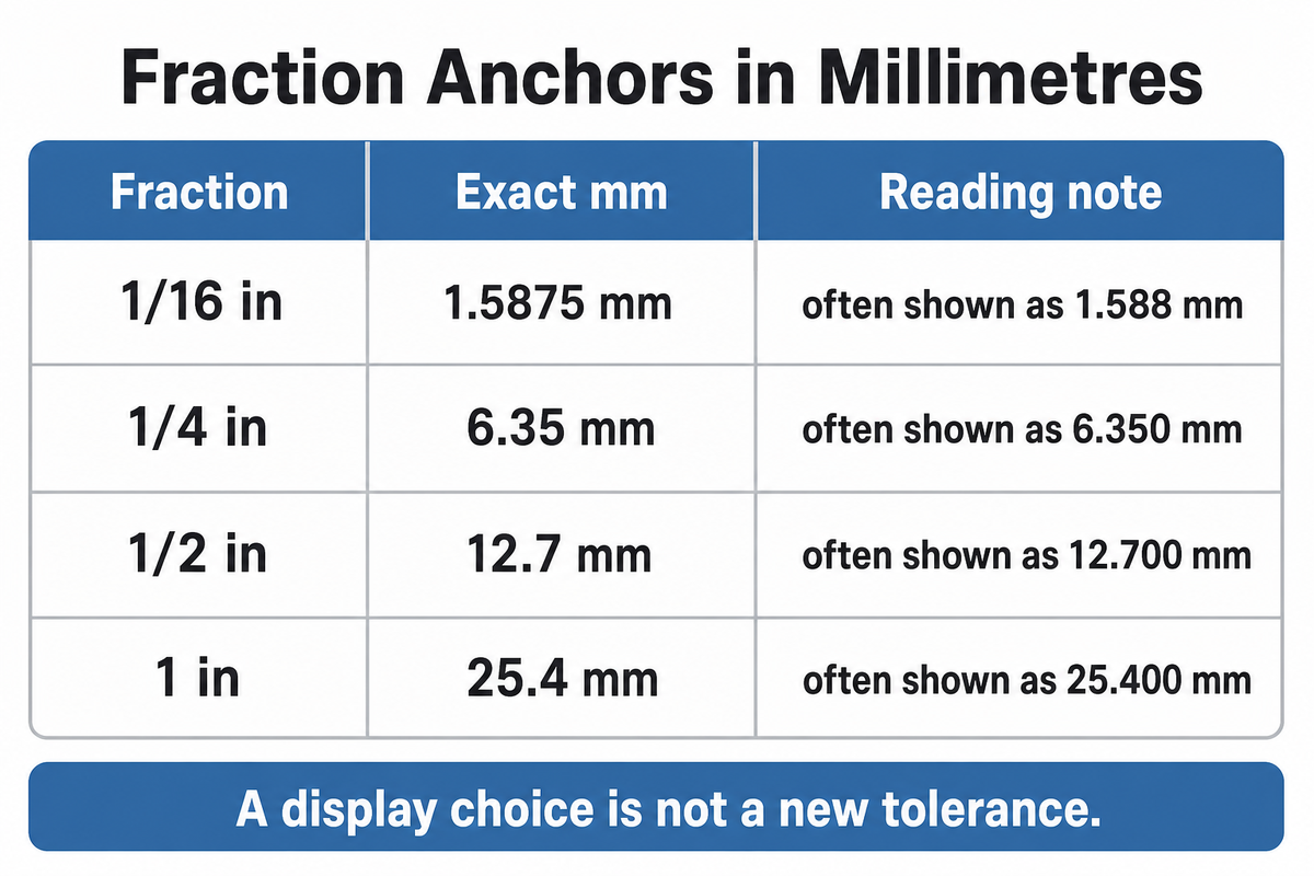
Fractional inch dimensions are common on shop sketches, fastener notes, hose sizes, and older equipment drawings. Convert the fraction to a decimal or multiply the numerator by 25.4 and divide by the denominator. The values below retain enough digits to show the exact arithmetic before an application-specific display decision.
| Fractional inch | Decimal inch | Exact millimetres | Common display |
|---|---|---|---|
| 1/64 in | 0.015625 in | 0.396875 mm | 0.397 mm |
| 1/32 in | 0.03125 in | 0.79375 mm | 0.794 mm |
| 1/16 in | 0.0625 in | 1.5875 mm | 1.588 mm |
| 1/8 in | 0.125 in | 3.175 mm | 3.175 mm |
| 3/16 in | 0.1875 in | 4.7625 mm | 4.763 mm |
| 1/4 in | 0.25 in | 6.35 mm | 6.350 mm |
| 5/16 in | 0.3125 in | 7.9375 mm | 7.938 mm |
| 3/8 in | 0.375 in | 9.525 mm | 9.525 mm |
| 1/2 in | 0.5 in | 12.7 mm | 12.700 mm |
| 5/8 in | 0.625 in | 15.875 mm | 15.875 mm |
| 3/4 in | 0.75 in | 19.05 mm | 19.050 mm |
| 7/8 in | 0.875 in | 22.225 mm | 22.225 mm |
| 1 in | 1.0 in | 25.4 mm | 25.400 mm |
This conversion table supports quick reading across the imperial and metric systems. The “common display” column is a reading aid, not a tolerance recommendation. Writing 6.350 mm doesn’t make a 1/4 in source dimension more exact than 6.35 mm. If the original drawing provides a title-block precision rule, use that rule or ask the drawing owner what the translated value should show.
Calculation capsule: Applying the NIST exact inch definition, 1/8 in is 3.175 mm and 1/16 in is 1.5875 mm. Rounding 1/16 in to 1.6 mm changes the display by 0.0125 mm; whether that matters depends on fit and tolerance.
The 25.4 One-Pass Method for Mixed Numbers
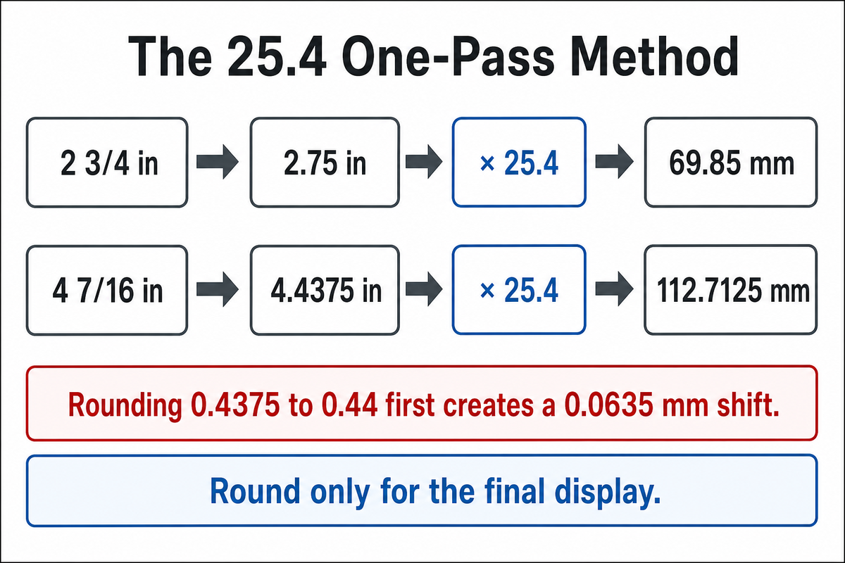
Mixed numbers invite avoidable rounding when the whole part and fractional part are converted separately, rounded, and added. The cleaner method reduces the input to one exact fraction or one decimal, multiplies once by 25.4, and rounds only for the final display. That keeps intermediate arithmetic from changing the answer.
25.4 One-Pass Method
Definition: Reduce the inch input once, multiply once by 25.4, and postpone display rounding until the end.
Consider 2 3/4 in:
- Convert the mixed number: 2 3/4 in = 2.75 in.
- Multiply once: 2.75 × 25.4 = 69.85 mm.
- Record 69.85 mm as the exact mathematical result.
- If the application calls for one decimal place, display 69.9 mm and retain 69.85 mm in the calculation record.
The same approach handles 4 7/16 in. Convert 7/16 to 0.4375, giving 4.4375 in. One multiplication produces 112.7125 mm. If you instead round 0.4375 in to 0.44 in before multiplying, the result becomes 112.776 mm, a 0.0635 mm shift created before the real conversion even starts.
Spreadsheets should follow the same sequence. Store the source value, its unit, and the unrounded converted value in separate cells. Apply formatting only to the display cell. That arrangement keeps a two-decimal presentation from overwriting a five-decimal working value and makes a later precision change traceable instead of forcing the team to reconstruct the calculation.
When you convert inch to millimeter values in a batch, test at least three anchors before release: 0 in must return 0 mm, 1 in must return 25.4 mm, and a known fraction such as 3/8 in must return 9.525 mm. These checks catch a reversed formula, an accidental division, and decimal-separator problems.
NIST Appendix B distinguishes exact conversion factors from rounded factors and advises that converted values retain a number of significant digits consistent with the possible rounding error in the original value. In practical terms, the exact factor doesn’t justify inventing certainty that the source dimension never contained.
Method capsule: The exact result for 4 7/16 in is 112.7125 mm. Prematurely replacing 7/16 with 0.44 changes the result to 112.776 mm, a 0.0635 mm difference. One-pass arithmetic preserves the source value; a later display rule controls how many digits the reader sees.
Nominal–Limit Separation Protocol for Toleranced Dimensions
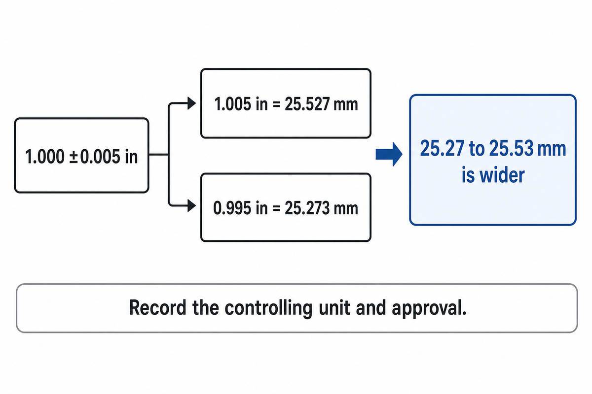
A tolerance-bearing dimension isn’t one number. It defines an interval between a permitted lower limit and upper limit. Converting only the nominal size and then attaching a separately rounded tolerance can move either boundary. The safer workflow converts both limits, retains guard digits, and records who controls final rounding and acceptance.
Nominal–Limit Separation Protocol
Definition: Convert minimum and maximum limits independently, preserve guard digits, and document the controlling unit and rounding decision.
Suppose a drawing states 1.000 ±0.005 in. Its actual inch limits are:
- Lower limit: 1.000 − 0.005 = 0.995 in
- Upper limit: 1.000 + 0.005 = 1.005 in
- Converted lower limit: 0.995 × 25.4 = 25.273 mm
- Converted upper limit: 1.005 × 25.4 = 25.527 mm
If someone converts the nominal value to 25.4 mm and rounds the tolerance from 0.127 mm to ±0.13 mm, the displayed limits become 25.27 to 25.53 mm. That interval is slightly wider than the exact 25.273 to 25.527 mm interval. The numbers look neat, but the acceptance boundary has changed.
Record these six fields before releasing a translated drawing:
- Source nominal dimension and source unit
- Source lower and upper limits
- Unrounded converted lower and upper limits
- Displayed precision and rounding method
- Controlling unit for inspection and acceptance
- Name or role of the person who approved the translation
NIST’s guidance for critical conversions tells users to know the rounding method and avoid overstating the final quantity. It doesn’t provide one universal decimal-place rule for every engineering application. For a contractual drawing, the drawing owner or designated engineering authority must decide whether a translated limit is controlling, reference-only, rounded inward, rounded outward, or shown with more digits.
Don’t hide the decision in a general note such as “all metric dimensions rounded.” State whether the inch limits or the millimetre limits govern inspection. If the metric values are reference-only, mark them that way on the drawing and in the request for quotation. If both unit sets appear controlling but disagree after rounding, stop the release and obtain one authoritative set.
Useful reviews compare intervals, not just centre values. Put the original lower limit beside the converted lower limit, and do the same for the upper limit. Then calculate any boundary shift introduced by the proposed display. This makes a 0.003 mm change visible even when both nominal values appear to match.
ISO 370:1975 was titled Toleranced dimensions, Conversion from inches into millimetres and vice versa, but ISO’s public catalogue now marks it withdrawn and lists no successor. Treat that page as historical status evidence, not as current operating instructions.
Limit capsule: A 1.000 ±0.005 in requirement has exact converted limits of 25.273 mm and 25.527 mm. Reporting it as 25.40 ±0.13 mm produces 25.27 to 25.53 mm instead. The translation record should expose that change before inspection criteria are released.
Drawing-to-RFQ Translation Register for Machine Dimensions
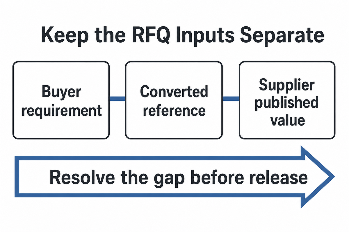
Industrial buyers often plan a machine envelope in inches while the supplier publishes metric dimensions. A translation register lets both sides compare values without quietly changing the commercial specification. It records the buyer’s inch requirement, its millimetre equivalent, the supplier’s published value, the numerical gap, and the status of that comparison.
Drawing-to-RFQ Translation Register
Definition: A handoff table that separates buyer requirements, converted references, supplier data, numerical gaps, and controlling approval.
| Buyer input type | Inch input | Converted result | Supplier/reference comparison | Required status |
|---|---|---|---|---|
| Whole-number envelope | 160 in max | 4064 mm max | UDTECH single-screw extruder page lists a 4000 mm water tank | Check total machine envelope and accessories |
| Decimal centre distance | 94.5 in | 2400.3 mm | Kraft paper page lists 2400 mm rail gauge | 0.3 mm gap is not equivalence proof |
| Web-width target | 63 in | 1600.2 mm | Kraft paper page lists 1600 mm net width | Confirm usable width and tolerance |
| Fractional diameter | 4 3/4 in | 120.65 mm | No supplier nominal assumed | Keep as a converted reference until model confirmation |
| Range | 4–6 in | 101.6–152.4 mm | Compare each endpoint | Do not convert only the midpoint |
| Symmetric tolerance | 1.000 ±0.005 in | 25.273–25.527 mm | No supplier tolerance assumed | Drawing owner approval |
| Unilateral tolerance | 2.000 +0.010/−0 in | 50.800–51.054 mm | Keep direction of the tolerance | Convert both limits |
| Reference dimension | 12 in REF | 304.8 mm REF | Reference remains reference | Not an acceptance limit |
| Standard-size callout | 1/2 in component | 12.7 mm arithmetic | A 12 mm standard component is different | Check standard, fit, thread, and interface |
The supplier comparisons above come from the live kraft paper machine page. They’re first-party commercial data, not independent certification. The page reviewed for this article didn’t publish tolerances for those dimensions. For any extruder machine project, final machine size, screw configuration, utilities, accessories, and available layout documents should be confirmed in the model-specific quotation.
If your starting point is a metric supplier dimension, use the swap button in the converter above or the full UDTECH millimeters to inches converter. The dedicated page includes a broader engineering unit set.
RFQ capsule: 94.5 in converts to 2400.3 mm, while UDTECH’s kraft paper machine page publishes a 2400 mm rail gauge. The 0.3 mm numerical gap doesn’t establish fit or non-fit because no tolerance was published on the reviewed page. Record it, then request confirmation.
When a Fractional Inch Is Not a Metric Substitute
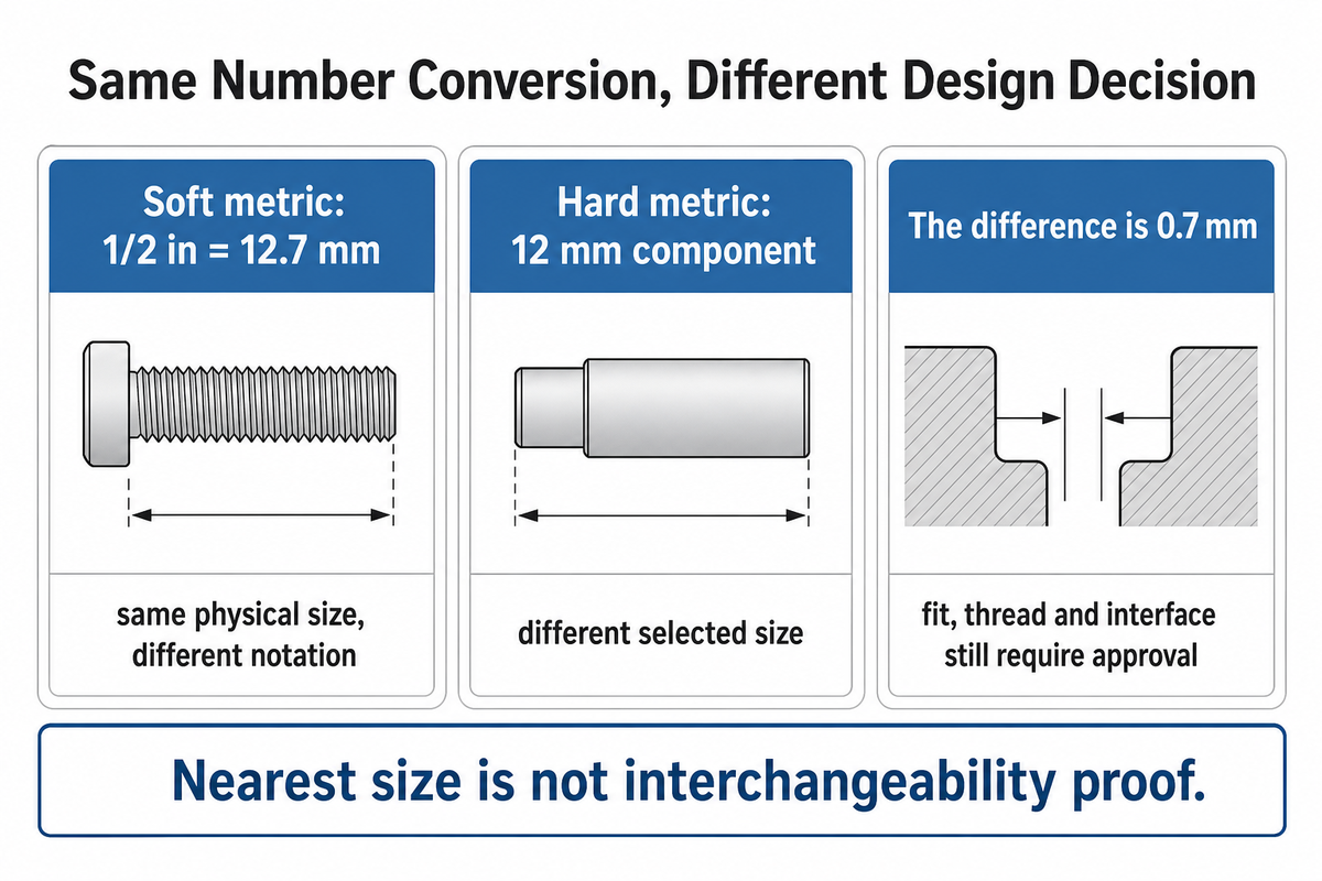
Mathematical equivalence and part replacement are different ideas. Soft metric conversion changes the notation while leaving the physical dimension unchanged. Hard metric selection uses a standard metric value, which may describe a different size. A hybrid specification contains both systems and must identify which value governs the interface and acceptance.
Acquisition.gov defines soft metric as the mathematical conversion of inch-pound measurements to metric equivalents while physical dimensions remain unchanged. It defines hard metric as using standard SI measurements in specifications, standards, supplies, and services. That distinction explains why 1/2 in = 12.7 mm arithmetically, but a 12 mm component isn’t automatically a 1/2 in substitute.
The difference is 0.7 mm. That may be irrelevant for a rough clearance dimension and unacceptable for a shaft, bearing, seal, thread, or tooling interface. A thread callout also carries pitch and form information; replacing its nominal diameter with a decimal millimetre value doesn’t convert the thread system.
- Use soft conversion when two teams need the same physical size shown in different units.
- Use hard metric selection only when the design authority has chosen a standard metric size and evaluated all interfaces.
- Use dual-unit or hybrid notation with a clear statement of which value controls.
- Never infer interchangeability from the nearest fraction alone.
Substitution capsule: 1/2 in equals 12.7 mm exactly, but 12 mm is 0.7 mm smaller. The conversion is soft metric if the 12.7 mm value describes the same item. Selecting a 12 mm standard item is a hard metric design choice that requires an interface check.
Why Conversion Practice Still Matters in Mixed-Unit Plants
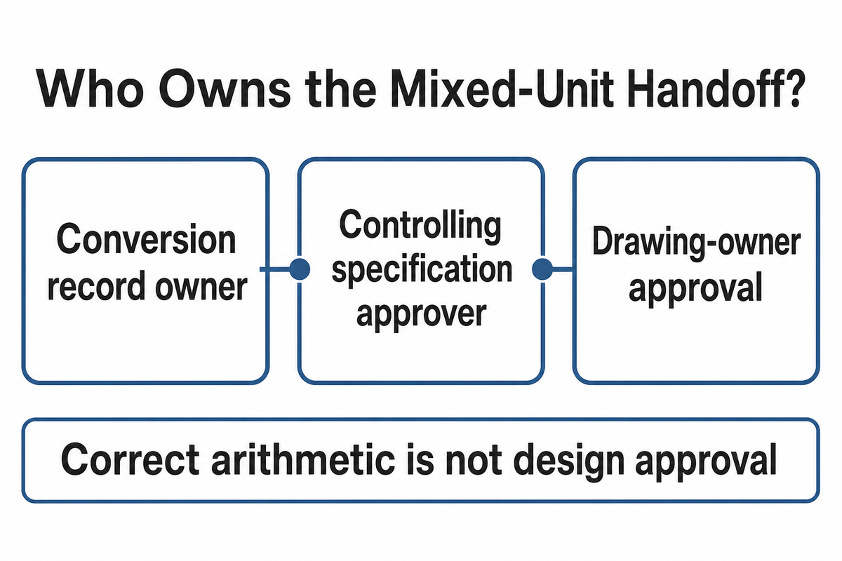
Modern software can multiply by 25.4 without difficulty. Errors persist because the software can’t decide what a drawing controls, whether a dimension is nominal or reference-only, whether a nearby standard size is acceptable, or how much precision the input justifies. Those questions belong to configuration control, inspection planning, and supplier communication.
Use the following release sequence for a mixed-unit handoff:
- Identify the source document, revision, unit, and title-block convention.
- Classify each value as nominal, limit, tolerance, basic, or reference.
- Convert once with 25.4 and retain guard digits in the calculation record.
- Convert limit endpoints independently.
- Label soft conversions as reference-only unless formally made controlling.
- Check hard metric substitutions against stock sizes, threads, fits, and mating interfaces.
- Obtain drawing-owner approval before releasing purchase or inspection criteria.
This sequence also prevents a common wording error: saying that millimetres are “more precise” than inches. Either unit can express fine resolution. Precision depends on the measurement system, stated digits, uncertainty, and tolerance. Application-appropriate conversion guidance therefore focuses on factors and rounding, not on declaring one unit inherently more precise.
Maintain the register through revisions. If a buyer changes 94.5 in to 94.25 in, the millimetre reference changes from 2400.3 mm to 2393.95 mm. The revised entry should point to the new drawing revision instead of silently replacing the old number. Procurement, engineering, and inspection then work from the same history.
For repeated jobs, assign one owner to the conversion record and one approver to the controlling specification. The owner verifies arithmetic and source revision; the approver decides fit, tolerance, standard size, and release status. That division keeps a correct calculation from being mistaken for design approval.
For an equipment request, send both the original inch requirement and the computed millimetre reference. Ask the supplier to reply with the model-specific metric value, permitted tolerance, overall envelope, utilities, and drawing revision. If the two values differ, resolve the interface rather than choosing the prettier number.
Release capsule: A 160 in maximum converts to 4064 mm. A page listing a 4000 mm tank doesn’t prove 64 mm of usable clearance because accessories and the total envelope may extend beyond the tank. Conversion starts the question; the approved layout drawing closes it.
Frequently Asked Questions
These answers cover the small conversions people search most often and the drawing decisions that calculators can’t make. Each number follows the exact 25.4 factor. When an answer mentions a rounded display, treat it as a reading convenience unless your drawing or inspection procedure explicitly gives that precision authority.
How many mm is 1/8 inch?
1/8 inch equals exactly 3.175 mm.
Divide 1 by 8 to get 0.125 in, then multiply 0.125 × 25.4 = 3.175 mm. If a general display shows 3.18 mm, it has rounded the exact mathematical result by 0.005 mm. For a part or drawing, keep 3.175 mm in the calculation record until you know the allowed precision.
Is 2 mm the same as 1/16 inch?
No. 1/16 inch is 1.5875 mm, not 2 mm.
The difference is 0.4125 mm. Those sizes might both work in a loose-clearance use, but they aren’t mathematically equal and shouldn’t be called interchangeable without a tolerance and interface check. If a standard component is specified as 1/16 in, convert it as 1.5875 mm reference-only rather than renaming it 2 mm.
Is 40 mm one inch?
No. One inch is exactly 25.4 mm, while 40 mm is about 1.5748 in; keep 40 mm controlling unless the design owner approves a substitute.
To check the reverse direction, divide 40 by 25.4. The result is approximately 1.574803 in. That isn’t 1 in and isn’t, by itself, a basis for selecting a standard fractional component. Keep the original 40 mm value as the controlling input until the design owner approves a substitute. Use the mm-to-inches tool when your source value starts in millimetres.
Is 10 mm the same as 1/4 inch?
No. One quarter inch is 6.35 mm.
A 10 mm value is 3.65 mm larger than 1/4 in. It’s approximately 0.3937 in, which is near 25/64 in but not equal to that fraction. Select a replacement only after checking the controlling standard and fit.
How do I convert 3/8 inch to mm?
3/8 inch equals exactly 9.525 mm.
Calculate 3 ÷ 8 = 0.375 in, then multiply 0.375 × 25.4 = 9.525 mm. Avoid rounding 0.375 before the multiplication.
How do I convert 2 3/4 inches to mm?
2 3/4 inches equals exactly 69.85 mm.
Convert the mixed number to 2.75 in, then multiply once: 2.75 × 25.4 = 69.85 mm. This is the 25.4 One-Pass Method.
How many decimal places should an inch-to-mm result have?
There is no universal decimal-place count for every application.
Keep guard digits during calculation, then report a precision consistent with the source value, drawing rule, measurement capability, and intended use. For critical conversions, document the rounding method and make sure the display doesn’t quietly alter an acceptance limit.
Need a Machine Quotation in Both Unit Systems?
Send UDTECH the original dimensions, units, limits, required interfaces, and drawing revision to request a model-specific quotation. Ask which metric layout documents are available for the selected configuration. Converted values remain reference-only until both sides identify and approve the controlling drawing before any production release.