

MM to Inches Converter
MM to inches is the conversion between the millimeter, the SI unit a metric drawing is dimensioned in, and the inch, the unit an imperial-market purchase order is written in. To convert mm to inches, divide the millimeter value by 25.4. The division is exact, not an approximation: the inch has been defined as exactly 25.4 millimeters since 1 July 1959. One millimeter is 0.0393700787 inch to nine significant figures; only the 25.4 direction is exact. A 25 mm shaft is 0.9843 inch, not 1 inch, and that 0.4 mm gap is 15.7 thousandths of an inch, enough to fail an interference fit.
25.4 mm = 1 in
1 in = 25.4 mm exactly, fixed by US Federal Register notice 59-5442 effective 1 July 1959. This tool divides by the exact factor and rounds the display to 4 decimals.
Division by the exact factor happens first; only the display is rounded. Use the swap button to run inches to mm, or change either unit to work in micrometers, thou, feet or yards. For the imperial side on its own, UDTECH’s guide to how many inches in a yard covers that conversion. Enter digits and a decimal point without a thousands separator.
Written out, the formula is inches = millimeters ÷ 25.4. Going the other way, multiply the inch value by 25.4. Both directions use the same exact factor, which is why a conversion table built from it never drifts no matter how far you extend it, and why two calculators that disagree aren’t rounding differently; they’re using different factors.

Millimeter to inch conversion table for common sizes
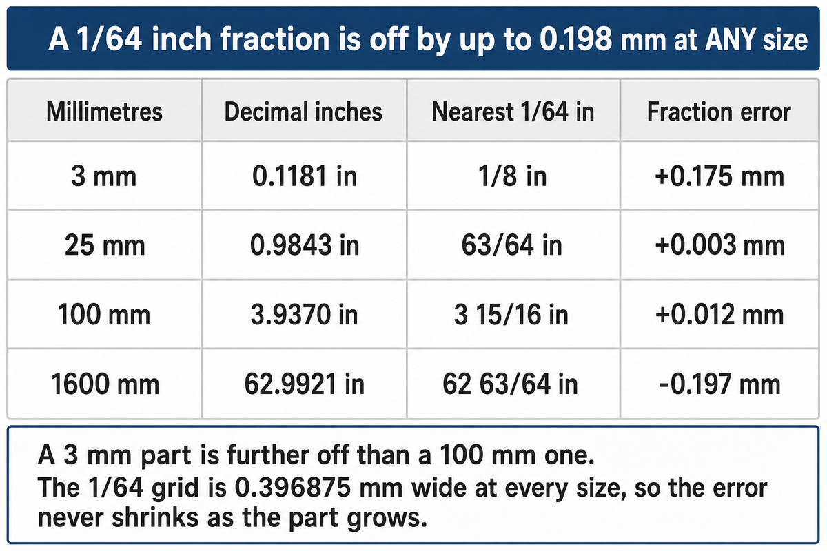
The table below carries every millimeter value people look up most, in decimal inches to four places and as the nearest 1/64 inch. The fourth column is the part other charts leave out: how far the fraction sits from the true value, in millimeters. Rounding to a fractional inch at 1/64 can be wrong by up to 0.198 mm.
| Millimeters (mm) | Inches (decimal) | Nearest 1/64 in | Fraction error (mm) |
|---|---|---|---|
| 1 | 0.0394 | 3/64 | +0.191 |
| 1.5 | 0.0591 | 1/16 | +0.087 |
| 2 | 0.0787 | 5/64 | -0.016 |
| 2.5 | 0.0984 | 3/32 | -0.119 |
| 3 | 0.1181 | 1/8 | +0.175 |
| 4 | 0.1575 | 5/32 | -0.031 |
| 5 | 0.1969 | 13/64 | +0.159 |
| 6 | 0.2362 | 15/64 | -0.047 |
| 8 | 0.3150 | 5/16 | -0.062 |
| 10 | 0.3937 | 25/64 | -0.078 |
| 12 | 0.4724 | 15/32 | -0.094 |
| 12.7 | 0.5000 | 1/2 | +0.000 |
| 13 | 0.5118 | 33/64 | +0.097 |
| 14 | 0.5512 | 35/64 | -0.109 |
| 15 | 0.5906 | 19/32 | +0.081 |
| 16 | 0.6299 | 5/8 | -0.125 |
| 20 | 0.7874 | 25/32 | -0.156 |
| 25 | 0.9843 | 63/64 | +0.003 |
| 25.4 | 1.0000 | 1 | +0.000 |
| 30 | 1.1811 | 1 3/16 | +0.162 |
| 40 | 1.5748 | 1 37/64 | +0.084 |
| 45 | 1.7717 | 1 49/64 | -0.153 |
| 50 | 1.9685 | 1 31/32 | +0.006 |
| 60 | 2.3622 | 2 23/64 | -0.072 |
| 70 | 2.7559 | 2 3/4 | -0.150 |
| 80 | 3.1496 | 3 5/32 | +0.169 |
| 90 | 3.5433 | 3 35/64 | +0.091 |
| 100 | 3.9370 | 3 15/16 | +0.012 |
| 120 | 4.7244 | 4 23/32 | -0.144 |
| 150 | 5.9055 | 5 29/32 | +0.019 |
| 200 | 7.8740 | 7 7/8 | +0.025 |
| 250 | 9.8425 | 9 27/32 | +0.031 |
| 300 | 11.8110 | 11 13/16 | +0.037 |
| 400 | 15.7480 | 15 3/4 | +0.050 |
| 500 | 19.6850 | 19 11/16 | +0.062 |
| 1000 | 39.3701 | 39 3/8 | +0.125 |
| 1600 | 62.9921 | 62 63/64 | -0.197 |
Two rows deserve a second look. At 25 mm the nearest 1/64 fraction is 63/64, which lands within 0.003 mm of the true value, finer than a shop rule can be read, since 1/64 inch is the finest fractional graduation Starrett lists on a precision inch rule, and combination rules pair 1/32 inch with 0.5 mm on one face and 1/64 inch with 1 mm on the other. At 1600 mm the same 1/64 rounding is 0.197 mm off, because the error of a fixed fraction grid doesn’t shrink as the part grows. Keeping large dimensions in decimal inches rather than fractions is the way out of that.
Every row above has its own page anchor, so a link to a single value works: append #mm-10, #mm-25 or #mm-100 to this page address to jump straight to that line.
The precision budget: how many digits to keep
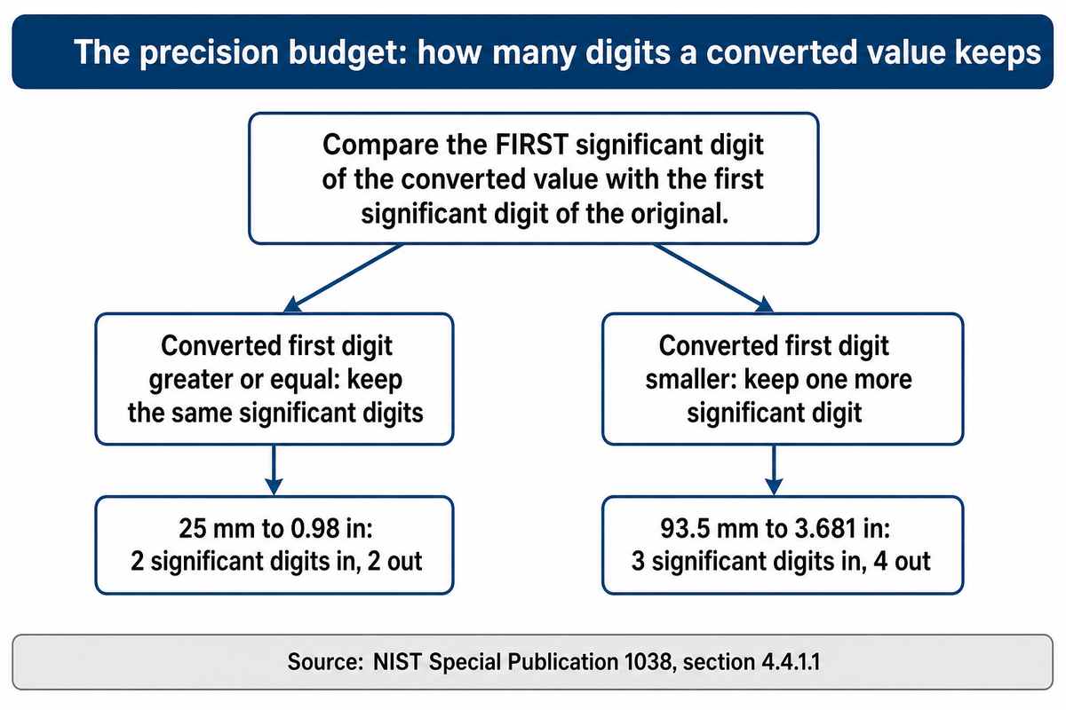
A calculator will hand you 3.681102362 inch for a 93.5 mm bore. Writing all ten digits onto a drawing claims a measurement precision nobody took. The National Institute of Standards and Technology sets the rule for how many digits survive a conversion, and it depends on the first digit of each number rather than on the size of the number.
If the first significant digit of the converted value is greater than or equal to the first significant digit of the original value, round the converted value to the same number of significant digits as there are in the original value.
— NIST Special Publication 1038, section 4.4.1.1, May 2006
The other half of the rule handles the opposite case: when the first significant digit of the converted value is smaller than the first significant digit of the original, keep one more significant digit. Call the result the precision budget: the number of digits a converted figure is entitled to carry. It’s set by the original measurement, not by the display width of the tool that did the arithmetic.
Worked through on a 93.5 mm bore: the original has three significant digits, the converted value 3.681102362 starts with 3, and 3 is smaller than 9, so the budget is four significant digits and the drawing figure is 3.681 inch. Run the same test on a 110.6 mm bore and the answer changes: the converted value starts with 4, which is larger than 1, so the budget stays at the original four digits and the figure is 4.354 inch. A plain 25 mm bar shows the rule changing the answer outright: two significant digits go in, the converted 0.984251968 starts with 9, and 9 is larger than 2, so two digits come out and the figure is 0.98 inch. Both bores land on three decimal places here, but for different reasons, and on other numbers the two branches give different answers.
NIST adds one procedural point that gets skipped in practice: rounding belongs at the end. Carry the full result through any intermediate arithmetic and round once, at the moment the number goes onto a document. Rounding at every step compounds the error you were trying to control.
Drawing offices that already publish to three decimal places in inches have their own house standard, and this rule doesn’t override it. What the precision budget adds is a defensible answer when a supplier asks why a figure carries three decimals and not five: 0.001 inch of implied precision, or 0.0254 mm, is the resolution the original millimeter figure supports. Same calculation, stated reason.
Converting a tolerance is not the same as converting a dimension
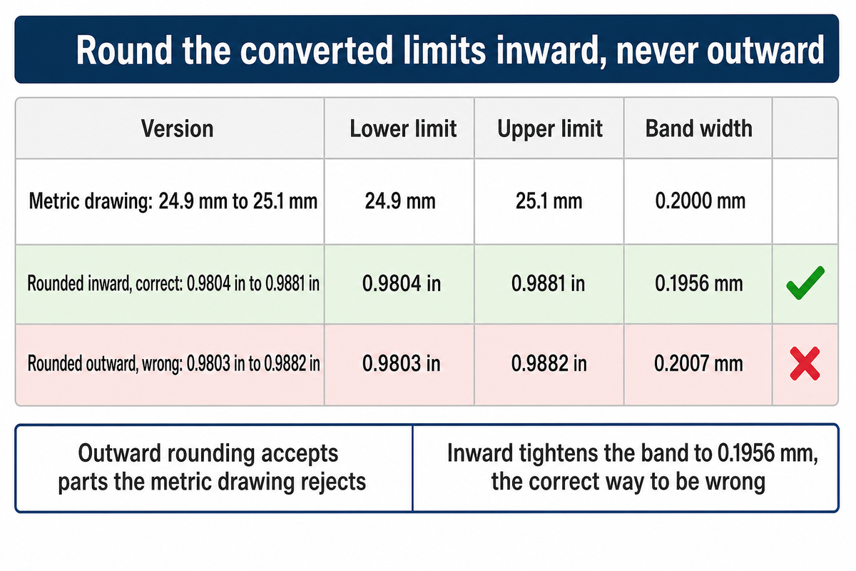
A nominal size can be rounded in either direction without consequence. A tolerance can’t. Round a converted limit outward and the acceptance band grows, which lets a part through that the original specification rejects. The rule is the same one NIST applies to any figure that acts as a maximum or a minimum.
Where an inch-pound unit represents a maximum or minimum limit (e.g., in a law or regulation), the rounding must be done in a direction where the metric value does not violate the original limit by increasing or decreasing it inappropriately.
— NIST Special Publication 1038, section 4.4.1, May 2006
Take a shaft called out as 25 mm +/- 0.1 mm. Convert the limits rather than the nominal: 24.9 mm is 0.980315 inch and 25.1 mm is 0.988189 inch. Rounded inward to four places, the inch callout becomes 0.9804 to 0.9881 inch. Rounded outward it would read 0.9803 to 0.9882 inch, and those two extra ten-thousandths widen the band to 0.2007 mm, accepting parts the metric drawing rejects. Inward rounding costs something too, and it is worth saying to a supplier before they find it themselves: at 0.1956 mm the converted band is 0.0044 mm tighter than the drawing, so a part sitting in the last few microns of the original tolerance now fails. That is the correct way to be wrong — a converted print should never accept what the original refuses.
How much precision the conversion has to preserve depends on the tolerance class the drawing invokes. ISO 2768-1:1989 covers dimensions carrying no individual tolerance, in four classes, and a drawing calls them up with a code such as ISO 2768-mK. The standard itself sits behind ISO’s paywall and is not quoted here; the deviation values below are the ones published by the machining supplier Fictiv, reproduced as a secondary source. ISO confirmed the 1989 text in a 2022 review and lists a replacement in progress under the geometrical product specification series, so check the class table against your own copy before writing it into a purchase specification.
| Basic size range (mm) | f (fine) | m (medium) | c (coarse) | v (very coarse) |
|---|---|---|---|---|
| 0.5 up to 3 | +/-0.05 | +/-0.1 | +/-0.2 | not specified |
| over 3 up to 6 | +/-0.05 | +/-0.1 | +/-0.3 | +/-0.5 |
| over 6 up to 30 | +/-0.1 | +/-0.2 | +/-0.5 | +/-1.0 |
| over 30 up to 120 | +/-0.15 | +/-0.3 | +/-0.8 | +/-1.5 |
| over 120 up to 400 | +/-0.2 | +/-0.5 | +/-1.2 | +/-2.5 |
| over 400 up to 1000 | +/-0.3 | +/-0.8 | +/-2.0 | +/-4.0 |
| over 1000 up to 2000 | +/-0.5 | +/-1.2 | +/-3.0 | +/-6.0 |
| over 2000 up to 4000 | not specified | +/-2.0 | +/-4.0 | +/-8.0 |
Read that table as a precision floor. A medium-class part between 6 mm and 30 mm carries +/-0.2 mm, which is 7.9 thousandths of an inch, so four decimal places in inches is already finer than the drawing needs. Move up to a medium-class weldment between 1000 mm and 2000 mm and the band is +/-1.2 mm, or 47 thousandths, which two decimal places will hold. Matching decimals to the tolerance class is what stops a converted drawing from implying a precision the shop was never asked to hit.
One historical note worth having when a supplier disputes the method: ISO published a standard for exactly this problem, ISO 370:1975 Toleranced dimensions: Conversion from inches into millimetres and vice versa, and withdrew it on 18 May 2000 without a replacement. Since then, how millimeter and decimal-inch dimensions and tolerances are written is governed by ASME Y14.5-2018, reaffirmed in 2024, while the rounding procedure itself comes from the NIST guidance quoted above. There is no single conversion standard to point at, which is why a stated method on the drawing beats an assumed one.
Machine dimensions in millimeters and inches
Capital equipment specifications are written in whichever unit the builder works in, and plants in the United States regularly evaluate metric machines. UDTECH’s own catalogue shows the split: laser lines publish both units, while extrusion and paper lines, which carry the largest dimensions on the site, published millimeters only when this page was written in August 2026.
Four families account for most industrial conversion traffic: steel plate thicknesses quoted in millimeters against an inch-based purchase order, pipe and tube dimensions, drilled hole and thread sizes, and machine envelope dimensions that decide whether a component clears a doorway. Engineering drawings that cross a border carry all four at once, which is why a fabrication quote is where unit errors surface.
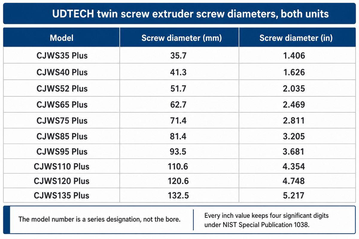
The ten models in UDTECH’s twin screw extruder screw diameter table are quoted to one decimal place in millimeters, so none of them lands on a round inch. Read the model number as a series designation rather than a measurement while you scan the table: CJWS52 Plus runs a 51.7 mm screw and CJWS135 Plus runs 132.5 mm, so the figure in the name brackets the class instead of naming the bore. Converted under the precision budget rule, every one keeps four significant digits:
| Model | Screw diameter (mm) | Screw diameter (in) | Significant digits kept |
|---|---|---|---|
| CJWS35 Plus | 35.7 | 1.406 | 4 |
| CJWS40 Plus | 41.3 | 1.626 | 4 |
| CJWS52 Plus | 51.7 | 2.035 | 4 |
| CJWS65 Plus | 62.7 | 2.469 | 4 |
| CJWS75 Plus | 71.4 | 2.811 | 4 |
| CJWS85 Plus | 81.4 | 3.205 | 4 |
| CJWS95 Plus | 93.5 | 3.681 | 4 |
| CJWS110 Plus | 110.6 | 4.354 | 4 |
| CJWS120 Plus | 120.6 | 4.748 | 4 |
| CJWS135 Plus | 132.5 | 5.217 | 4 |
The same arithmetic runs across the rest of the catalogue. On the kraft paper machine specification, a 1600 mm net paper width is 62.99 inch and a 2400 mm rail gauge is 94.49 inch; both matter at the building stage, because a rail gauge decides the floor layout before the machine ships. The single screw extruder page gives a 120 mm screw, 4.724 inch, and a 4000 mm water tank, 157.5 inch, which is the length that has to fit the bay.
Precision requirements climb at the other end of the size range. The 20 W fiber laser marking machine is specified at +/-0.01 mm positioning accuracy, which is 0.0004 inch, four ten-thousandths, and sits below the resolution of a standard dial caliper. A converted figure carrying two decimal places in inches can’t express that number at all, which is the clearest case for letting the precision budget, rather than habit, set the decimal count. Browse the full extruder machine range in millimeter dimensions if you need the rest of the bores.
When the nearest fraction is not a substitute
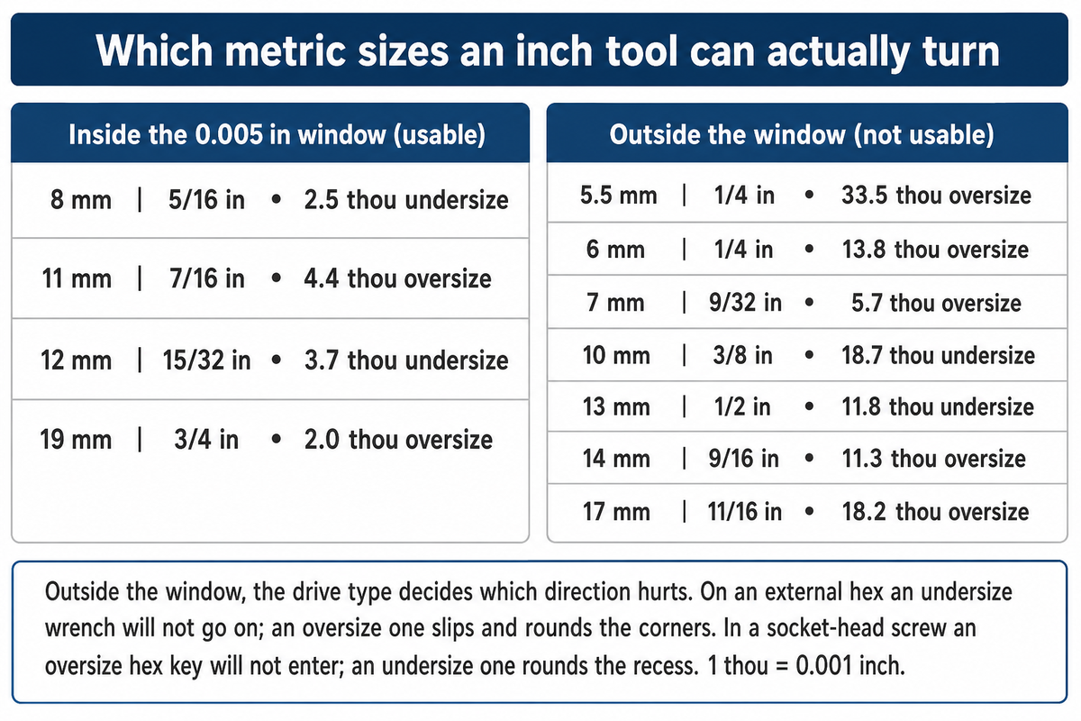
Charts that name the nearest imperial size answer a geometry question, not a fitting question. Tool makers publish a working limit for interchangeability of about 0.005 inch, or 0.127 mm, between the fastener and the tool that turns it; it is shop practice, not a standard. Past that gap, contact moves off the flats and onto the corners of the fastener.
Treat the 0.005 inch figure as shop practice from the people who sell the tools rather than as a tolerance from a standard: the dimensional limits for wrench openings live in assembly-tool standards, and this is the rule of thumb sitting on top of them. Each metric size below sits against its arithmetically nearest common inch size. The gaps are computed from the exact 25.4 mm factor rather than copied from a chart, and the last column applies the 0.005 inch working limit to each one:
| Metric size | Exact inches | Nearest inch size | Gap (thousandths of an inch) | Inside the 0.005 in limit |
|---|---|---|---|---|
| 5.5 mm | 0.2165 | 1/4 in | +33.5 | No |
| 6 mm | 0.2362 | 1/4 in | +13.8 | No |
| 7 mm | 0.2756 | 9/32 in | +5.7 | No |
| 8 mm | 0.3150 | 5/16 in | -2.5 | Yes |
| 10 mm | 0.3937 | 3/8 in | -18.7 | No |
| 11 mm | 0.4331 | 7/16 in | +4.4 | Yes |
| 12 mm | 0.4724 | 15/32 in | -3.7 | Yes |
| 13 mm | 0.5118 | 1/2 in | -11.8 | No |
| 14 mm | 0.5512 | 9/16 in | +11.3 | No |
| 17 mm | 0.6693 | 11/16 in | +18.2 | No |
| 19 mm | 0.7480 | 3/4 in | +2.0 | Yes |
One of the four passing pairs carries a catch. The 15/32 inch size that comes out arithmetically nearest for 12 mm is missing from most ordinary inch socket sets, as is the 9/32 inch nearest 7 mm, which is why published charts disagree with each other: some list the nearest size that exists in a normal set rather than the nearest size that exists in geometry. When two charts contradict each other on the same pair, that difference in method is usually the reason.
Direction decides how badly a mismatch ends, and which direction is the dangerous one flips with the drive type. On an external hex, a wrench or socket that is undersize simply will not go over the head, so the mistake announces itself; the oversize one slips on, sits loose on the corners and rounds them off under torque. Inside a socket-head screw the failure runs the other way: an oversize hex key will not enter the recess at all, while an undersize key enters, feels normal under light load and rounds the recess from the inside until the screw has to be drilled out. Hex keys also tighten the limit to roughly 0.003 inch, because the tool bears inside a closed recess with nothing outside to hold it square. In both cases the damage is done by whichever tool fits loosely — only the word for it changes.
The second inch the United States retired in 2023
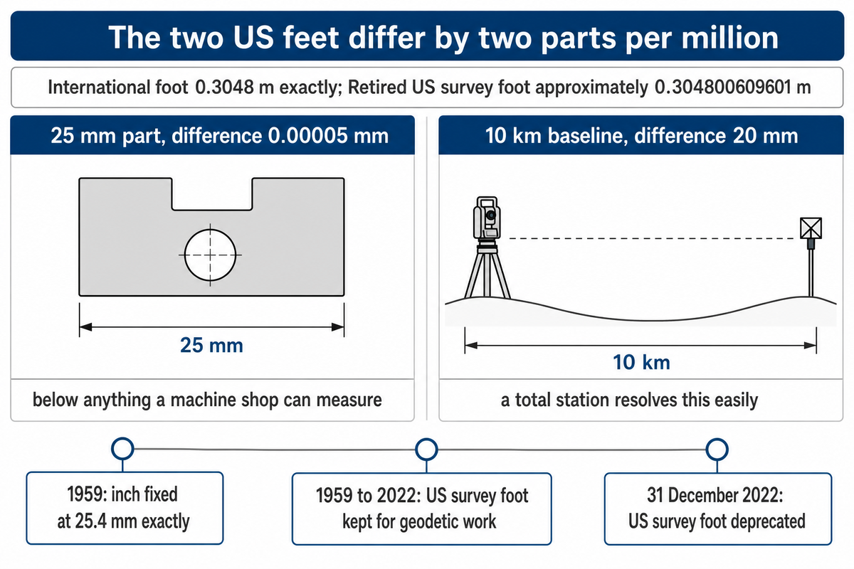
For sixty-three years the United States carried two inches. The international inch of 25.4 mm exactly served manufacturing, while the survey inch, derived from the pre-1959 foot of 1200/3937 metre, stayed alive for geodetic work. NIST states the relationship exactly: one international foot is 0.999998 US survey foot, a difference of two parts in a million.
That carve-out ended. NIST and the National Oceanic and Atmospheric Administration deprecated the US survey foot as of 31 December 2022, and since 1 January 2023 the country has had one approved definition of the foot, the international foot of 0.3048 metre exactly, which superseded the survey foot. NIST publishes the two side by side: 0.3048 m exactly against approximately 0.304800609601 m for the retired survey foot.
Two parts per million is 0.00005 mm on a 25 mm part, far below anything a machine shop can measure, so this changes nothing for equipment work. It changes plenty over long distances: across a 10 km survey baseline the same ratio is 20 mm. If you inherit coordinates or plant boundary data recorded before 2023, the unit they were captured in is worth confirming before it’s converted.
Three checks settle which foot a legacy file used, in order of effort. First, read the title block or the file metadata: survey-based state plane coordinate data is normally labelled US survey foot or usft outright. Second, if the document gives both a metric and an imperial figure for the same long dimension, divide one by the other: 0.3048 exactly means international foot, and 0.304800609601 means survey foot. Third, if only one unit is present, convert a known long baseline both ways and see which result matches the field measurement: on a 10 km line the two answers sit 20 mm apart, which a total station resolves easily. Below roughly 1 km the difference drops under 2 mm and stops mattering for anything but geodetic control.
Frequently asked questions
Is 14 mm 1 inch?
No. 14 mm is 0.5512 inch, a little over half an inch, against 25.4 mm for a full inch. Its nearest 1/64 fraction is 35/64 inch. For a fastener, the closest inch size is 9/16 inch, still 11.3 thousandths away.
Is 5 mm equal to 1/4 of an inch?
No. 5 mm is 0.1969 inch against 0.25 inch, a gap of 0.053 inch or 1.35 mm — far too wide to treat as one size. Rounded to the nearest 1/64, 5 mm is 13/64 inch, and a true quarter inch is 6.35 mm.
Is 12 mm close to 1/2 inch?
Close, but not interchangeable: 12 mm is 0.4724 inch against 0.5000 inch, a gap of 27.6 thousandths of an inch, which is more than five times the 0.005 inch working limit that tool makers publish. A 1/2 inch socket on a 12 mm head turns under light load, then rounds the flats once torque comes on. The nearest inch size inside the limit is 15/32 inch, at 3.7 thousandths, which most socket sets do not carry.
What is 1 inch in mm exactly?
Exactly 25.4 mm. The value is a definition rather than a measurement. The US National Bureau of Standards adopted it effective 1 July 1959 and recorded in the same notice that the American Standards Association had already approved 25.4 mm as ASA B48.1-1933, and it hasn’t changed since.
How is rounding handled in this converter?
Four decimal places, applied to the display only. Division uses the exact factor of 25.4 and the full value is kept through the arithmetic, which follows the NIST instruction to round once at the end rather than at every step. Four decimals resolves 0.0001 inch, or 0.00254 mm, well past what a shop instrument can follow.
Trailing zeros are trimmed, so 25.4 mm reads as 1 in rather than 1.0000 in, and any result smaller than 0.0001 switches to six significant figures instead of collapsing to a misleading zero. For a figure going onto a drawing, apply the precision budget rule above instead of copying all four decimals across: high precision on paper that nobody measured is the error the rule exists to prevent.
Will tolerances change after I convert the units?
The physical tolerance stays the same; only its numerical expression changes, and careless rounding corrupts it. Convert the two limits separately, not the nominal, and round each inward. A 25 mm +/- 0.1 mm shaft becomes 0.9804 to 0.9881 inch.
Where can I find the official reference standards?
Three documents cover it. The 1959 Federal Register notice fixes the inch at 25.4 mm, NIST Special Publication 1038 gives the rounding procedure, and the BIPM definition of the metre anchors the millimeter to the speed of light at 299 792 458 m/s.
Is a millimetre the same as a millimeter?
Yes, two spellings for one unit of length. Metre is the international form used by the BIPM and the SI brochure; meter is standard American usage, and either spelling of millimetre names one thousandth of a metre. Neither spelling changes the arithmetic: the millimeter belongs to the metric system, the inch to the United States customary system, and the equivalence between them was fixed by agreement rather than by measurement.
Any unit of measurement in the metric column of a specification has an exact inch equivalent and converts the same way whichever spelling the document uses.
References & Sources
- National Bureau of Standards, Refinement of Values for the Yard and the Pound, Federal Register Doc. 59-5442 (1959)
- NIST Special Publication 1038, The International System of Units (SI): Conversion Factors for General Use (May 2006)
- NIST Special Publication 811 Appendix B, Conversion Factors
- NIST Office of Weights and Measures, SI Units: Length
- NIST and NOAA, Deprecation of the United States Survey Foot, Federal Register (5 October 2020)
- NIST, US Survey Foot: Revised Unit Conversion Factors
- BIPM, SI Base Unit: the Metre
- ISO 370:1975, Toleranced dimensions: conversion from inches into millimetres and vice versa (withdrawn 2000)
- ASME Y14.5-2018 (R2024) — Dimensioning and Tolerancing
- ISO 2768-1:1989, General tolerances, Part 1: tolerances for linear and angular dimensions without individual tolerance indications (ISO catalogue entry; full text is paywalled)
- ISO 2768 general tolerance classes and permissible deviation values, as published by Fictiv (secondary source for the table reproduced above)
- Teng Tools, Metric to standard wrench conversion chart and the 0.005 inch interchangeability limit
- Starrett, precision rule graduations, including 1/64 inch and 0.5 mm faces
Reviewed by the UDTECH technical team. Machine dimensions are quoted from UDTECH product pages and converted with the exact 25.4 mm factor; the conversion rules are the ones set out in the NIST publications listed above. Need a specification checked in your own units before you quote a job? Send the drawing to UDTECH and we will return the figures in both.