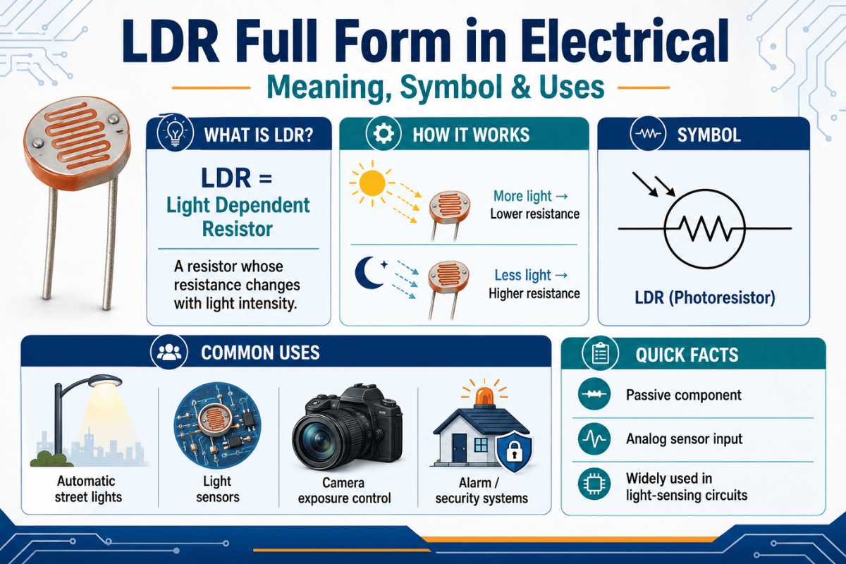
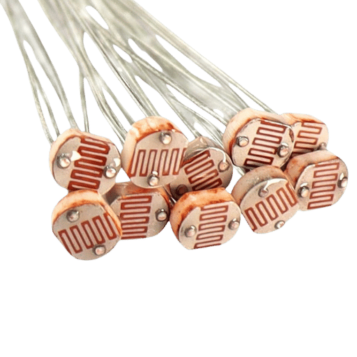
The LDR full form in electrical and electronics work is Light Dependent Resistor. An LDR is a passive, two-terminal semiconductor component, also called a photoresistor, photoconductive cell, or CdS cell, whose electrical resistance drops as the light falling on it gets brighter, and rises again in the dark. That single behavior is why LDRs sit inside street lights, alarms, and cameras.
LDR Quick Facts
| Full form | Light Dependent Resistor (LDR) |
| Also called | Photoresistor, photoconductive cell, photocell, CdS cell |
| Type | Passive, non-polarized (works either way round) |
| Material | Cadmium sulfide (CdS) or cadmium selenide (CdSe) |
| Dark resistance | ~1 MΩ (up to 10 MΩ on larger cells) |
| Bright-light resistance | ~100 Ω to 1 kΩ |
| Response time | ~10 to 100 ms (slow for an electronic part) |
| Peak sensitivity | ~540 nm (green, in the visible band) |
| Symbol | A resistor body with two arrows pointing in |
Typical values for common 5 mm CdS cells. Updated June 2026.
What Is the Full Form of LDR? (Meaning & Definition)
LDR stands for Light Dependent Resistor. As a light-dependent resistor, its value isn’t fixed: it changes with the amount of light reaching its surface. Engineers and datasheets also call the same part a photoresistor, a photoconductive cell, a photocell, or, after its most common material, a CdS cell. All five names describe one device.
Why does one part carry so many names? History. The “LDR” label is common in school physics and in British and Indian engineering courses, while datasheets and physics resources such as HyperPhysics usually print “photoresistor.” If you see any of those words on a circuit diagram or a parts list, they all point to one light-sensitive resistor. It’s a passive component, meaning it has no power gain of its own; it simply reacts to light, the way a plain resistor reacts to a fixed value.
How Does an LDR Work? (Photoconductivity)
An LDR works on photoconductivity: light striking the semiconductor frees electrons, which lowers the material’s resistance. In the dark, the cadmium-sulfide film hold its electrons tightly, so it behaves like a high-value resistor. When light hits it, the resistance fall, often by a factor of a thousand or more.
To go one level deeper, the mechanism follows the band-gap rule. A photon only frees an electron if it carries energy equal to or greater than the semiconductor material’s band gap. CdS has a band gap near 2.4 eV, which lines it up neatly with visible light, the same photoconductivity in cadmium sulfide that thin-film light sensors rely on. As light intensity increases and enough photons arrive, electrons jump from the valence band to the conduction band, the number of charge carriers climbs, and the resistance decrease. Remove the light and the electrons fall back, so resistance climbs again.
“Low cost, two lead photoresistors using a cadmium sulfide (CdS) element show a dramatic decrease in resistance when illuminated, and are commonly used as a light sensing element.”
The 1000× Rule
📐 Engineering Note
A common CdS cell sits near 1 MΩ in darkness and drops to roughly 1 kΩ in normal room light, about a 1000× swing. Push it into bright sunlight and some cells fall under 100 Ω, stretching the swing past 10,000×. That huge ratio, not precision, is what makes the LDR useful: it turns “light or dark” into an easy-to-read change in resistance.
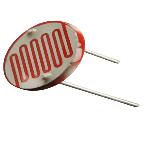
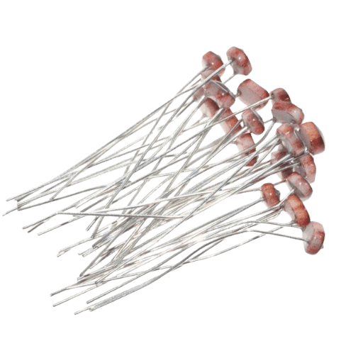
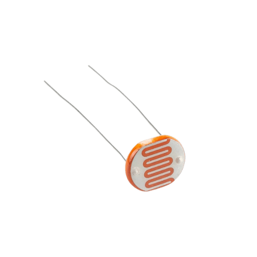
Why is an LDR built in a zig-zag shape?
An LDR’s cadmium-sulfide film is laid down in a winding, snake-like track between two metal contacts, and that “Snake-Track” layout is deliberate. A long, narrow strip packs the most light-sensitive length into a small window while keeping the two electrodes close, so the cell reach a useful resistance and power rating without needing a large surface.
In other words, the serpentine path maximizes the illuminated semiconductor sitting between the terminals, more exposed track means a bigger, more usable resistance change for the same chip size.
LDR Symbol and Circuit Diagram
An LDR symbol is drawn as a resistor, a rectangle in IEC drawings, or a zig-zag line in older American schematics, with two arrows pointing inward toward it. Those two arrows mean “incident light,” the same arrows used on a photodiode symbol; the difference is that the LDR body is a resistor, not a diode. The part has two identical terminals and no polarity marking, so it can be wired either way round.
On its own, a changing resistance is hard to read. That’s why an LDR almost always appears inside a voltage divider: the LDR and a fixed resistor are connected in series across the supply, and the junction between them gives an output voltage that rises or falls with light, the same arrangement drawn in published LDR control-circuit diagrams. That voltage is what a microcontroller or comparator actually measures.
LDR Resistance: Dark vs Light (Real Numbers)
Every LDR’s headline spec is its dark-to-light resistance swingits resistance vary with each change in light, from mega-ohms in the dark to a few hundred ohms in bright light, the photoconductive response measured directly in cadmium-sulfide films. The table below pulls the nominal figures for the popular GL55 series of 5 mm CdS cells into one place, the number in each part code roughly tracks its 10-lux resistance, so a GL5506 is the “fast and low” end and a GL5549 is the “high resistance” end.
| Part | Resistance at 10 lux | Dark resistance (0 lux) | Gamma (γ) | Peak λ |
|---|---|---|---|---|
| GL5506 | 2–5 kΩ | ≥0.2 MΩ | 0.5 | 540 nm |
| GL5516 | 5–10 kΩ | ≥0.5 MΩ | 0.6 | 540 nm |
| GL5528 | 8–20 kΩ | ≥1.0 MΩ | 0.7 | 540 nm |
| GL5537 | 16–50 kΩ | ≥2.0 MΩ | 0.7 | 540 nm |
| GL5539 | 30–90 kΩ | ≥5.0 MΩ | 0.8 | 540 nm |
| GL5549 | 50–100 kΩ | ≥10 MΩ | 0.8 | 540 nm |
Source: GL55-series CdS photoresistor datasheets (Sparkfun, Handson Technology). Values are nominal, see the field note below on unit-to-unit spread.
In one published bench test, eight GL5528 cells from the same batch read anywhere from 524 to 861 on the same 10-bit analog input under identical light, a spread wide enough that no single cell can be trusted to match another. Bins are wide, and sellers often ship whichever GL type is in stock, so treat the datasheet figure as a starting point and calibrate each unit when the reading matter.
Types of LDR (and the Cadmium / RoHS Angle)
LDRs are grouped two ways: by how the semiconductor is doped, and by which part of the light spectrum they sense. An intrinsic LDR uses a pure semiconductor and needs more light energy to conduct; an extrinsic LDR adds doping so it responds with less energy and reaches further into the infrared. The material chosen set the wavelength the cell “sees” best.
| Material | Doping type | Sensitive band | Typical use |
|---|---|---|---|
| Cadmium sulfide (CdS) | Intrinsic/extrinsic | Visible (~540 nm) | The everyday LDR |
| Cadmium selenide (CdSe) | Extrinsic | Visible–red (~720 nm) | Red-shifted light sensing |
| Cadmium telluride (CdTe) | Extrinsic | Visible | Specialist visible cells |
| Lead sulfide (PbS) | Extrinsic | Near-infrared | IR detection |
| Lead selenide (PbSe) | Extrinsic | Mid-infrared | Thermal/IR sensing |
| Indium antimonide (InSb) | Extrinsic | Infrared | Scientific/defense IR |
| Germanium (Ge) | Intrinsic | Infrared | Long-wavelength cells |
| Indium phosphide (InP) | Extrinsic | Infrared | Optoelectronic IR |
| Silicon (Si) | Intrinsic | Visible–near-IR | Pure-semiconductor cells |
Compiled from photoresistor material datasheets (electricaltechnology.org; ScienceDirect, Photoresistors topic).
Here is the part most beginner guides skip: cadmium is a restricted substance. The EU RoHS Directive caps cadmium at 0.01% by weight in a homogeneous material, and a CdS cell sits well above that line. So CdS LDRs are largely designed out of new RoHS-compliant EU electronics. They have not vanished, though: they stay common in markets outside the EU, in legacy and replacement parts, and across the hobby world, where the cadmium limit does not apply. That regulatory pressure is the main force pushing new designs toward cadmium-free photodetector designs such as photodiodes and phototransistors.
What Is an LDR Used For? (Applications)
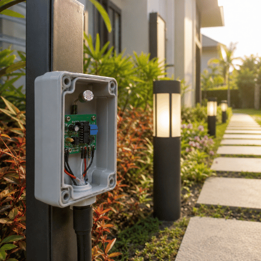
An LDR is used wherever a circuit needs a cheap “is it light or dark?” decision rather than a precise reading. A classic example is the dusk-to-dawn street light: the LDR’s resistance climbs past a set threshold near 10 lux at dusk, a comparator flips, and a relay switches the 230 V lamp on, no human and no timer needed. Published street-light automation studies typically switch the lamp on below roughly 20 lux and off above 40 lux.
- ✔ Street & garden lightingautomatic dusk-to-dawn switching to save energy
- ✔ Burglar alarmsa steady beam on the LDR; break the beam and the resistance change trips the alarm
- ✔ Camera exposure / phone brightnessmeasuring ambient light to set a level
- ✔ Object counters on a line, each item that breaks the beam adds a count
- ✔ Solar trackers & clock radiospointing panels at the sun, or dimming a display at night
A real-world case show the pattern. On a solar garden light, a single GL5528 and one fixed resistor tell the controller when the sun has set; the same cell, read the other way, tells it when there’s enough daylight to recharge. One 10-cent part runs the whole day/night cycle, which is exactly why LDRs remain common in low-cost, high-volume products even as regulations tighten.
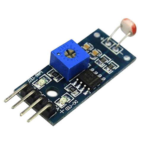
How to Use an LDR in a Circuit (Voltage Divider & Arduino)
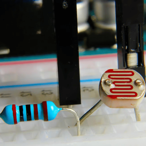
To use an LDR in a circuit, wire it with a fixed resistor as a voltage divider, then read the junction voltage with a comparator or a microcontroller’s analog input and act on a threshold. That arrangement turn the cell’s changing resistance into a clean voltage your circuit can use, the rest is choosing the resistor value and deciding where “light” becomes “dark.”
What component is used with an LDR in a voltage divider?
A fixed resistor is the partner an LDR needs in a voltage divider. The LDR and the resistor sit in series between the supply and ground, and the junction between them feeds the output. As light changes the LDR’s resistance, that junction voltage moves up or down. A good starting value for the fixed resistor is near the geometric mean of the cell’s dark and light resistance, which keeps the output near mid-supply across the working range.
For a GL5528, a 10 kΩ fixed resistor is the common, practical choice; many published circuits use 10 kΩ or 22 kΩ. Feed the divider output to an Arduino’s analog pin, on a 3.3 V or 5 V rail, and analogRead() returns a number from 0 to 1023 that climbs and falls with light, the same read-and-threshold approach used in Arduino-based LDR controllers. From there it’s a software threshold: above a value means “bright,” below means “dark.”
📐 Engineering Note
That fixed resistor isn’t optional. Without it the LDR has nothing to divide against, the input floats, and the reading is meaningless, the resistor both sets the divider and limits current. One practical trick when driving an LED display: take the square root of the raw reading before using it, so the brightness track how the human eye actually adapts to dark and light.
LDR vs Photodiode vs Phototransistor: Which Light Sensor?
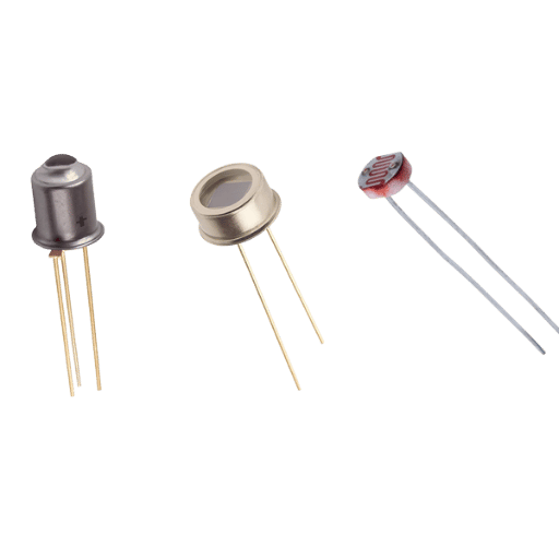
An LDR is the right light sensor when you need cheap on/off sensing over a wide area, and the wrong one when you need speed or accuracy. The table make the trade clear, and the rule under it, the Light-Sensor Pickturns it into a one-line decision.
| Feature | LDR (photoresistor) | Photodiode | Phototransistor |
|---|---|---|---|
| Response speed | Slow (10–100 ms) | Very fast (<1 µs) | Fast (µs) |
| Linearity | Non-linear | Highly linear | Moderately linear |
| Output | Resistance (analog) | Current (analog) | Current (analog) |
| Polarity | None (either way) | Polarized | Polarized |
| Relative cost | Lowest | Low–moderate | Moderate |
| Best for | Day/night on-off | High-speed / precise | Moderate-speed switching |
Light-Sensor Pick — the one-line rule
- Need a cheap “light or dark” trigger over a wide area? → LDR.
- Need speed (above ~1 kHz) or a true light-level reading? → photodiode.
- Need a middle ground, more output than a photodiode, faster than an LDR? → phototransistor.
A common mistake is reaching for an LDR to measure light. Because the cell is non-linear, temperature-sensitive, and varies part to part, it’s poor at reporting an exact lux valuesensor-comparison research notes that photodiodes give a linear, quantitative response where LDRs don’t. Use it as a threshold sensor, and switch to a photodiode when the number itself has to be right.
Testing an LDR & Common Problems
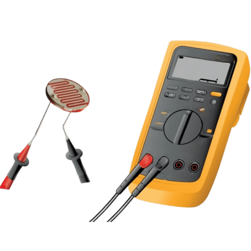
You can test an LDR in under a minute with a multimeter set to ohms. Touch the two leads, read the resistance in normal light, then cover the cell with your hand: the value should jump from a few kilo-ohms up into the mega-ohm range, the photoconductive resistance change characterised for CdS sensors. If it does, the cell is alive; if it stays flat, it’s dead or open. Because the LDR has no polarity, it doesn’t matter which lead touches which probe, and the cell works on AC or DC alike.
Two more quick answers settle most beginner questions. An LDR is an analog device, it gives a continuous range of resistance, not a two-state on/off output, and it’s passive, because it only reacts to light and adds no power gain of its own.
- Slow response10–100 ms; it can’t follow fast flicker or pulses
- Temperature driftspecs are rated near 25 °C, and sensitivity falls as the cell warms
- Light “memory” (hysteresis)it can take a few seconds to recover its dark value after a bright flash
- Long-term ageingdark resistance can drift down over months, and UV in sunlight speeds the drift
- Unit-to-unit spreadcalibrate each cell where the threshold matter
From Hobby LDRs to Industrial Light Sensing
An LDR earns its place at the low-cost, low-stakes end of light sensing, and the market reflects that steady role. Estimates vary with how “photoresistor” is scoped, but the discrete-component market is put at roughly $240–350 million in 2025, growing about 7% a year (Report Prime; Future Market Report). Growth is real but modest, because the part is mature: patent activity in light sensing has moved toward cadmium-free photodiodes, phototransistors, and perovskite photodetectors rather than new CdS cells.
Two forces shape the next few years. RoHS and similar rules keep narrowing where cadmium is allowed, pushing designers to CdS-free parts; and smart LED street lighting, a 2026 growth area, increasingly pairs light sensing with networked controls rather than a bare photocell. Practical takeaway: for a simple ambient on/off, an LDR is still the cheapest answer; for speed, accuracy, or anything that must pass regulatory review, plan for a photodiode or phototransistor from the start.
That same jump from “good enough” to “must be exact” is the daily reality in factory automation. Industrial machines, the kind built by manufacturers like industrial CNC and laser machinesrely on fast, repeatable photoelectric and optical sensing for safety interlocks and positioning, not on hobby-grade CdS cells. If you’re moving from a breadboard LDR toward production equipment, the control systems behind a CNC laser cutting machine and the broader family of CNC machine types show where light sensing goes when precision and reliability become non-negotiable. Precision laser marking systems apply the same idea.
Frequently Asked Questions
Q: What is an LDR used for?
View Answer
Q: Is an LDR analog or digital?
View Answer
analogRead() — and apply a threshold in software. The cell itself stays analog; the conversion to a digital value happens downstream.Q: Are LDR sensors AC or DC?
View Answer
Q: Is an LDR passive or active?
View Answer
Q: What is the dark resistance of an LDR?
View Answer
Q: Can an LDR detect infrared or colour?
View Answer
Q: What can replace an LDR in a circuit?
View Answer
References & Sources
- Photodetectors and Photoconductive CellsHyperPhysics, Georgia State University
- Photoconductivity in cadmium sulfide nanostructuresNIH National Library of Medicine (PMC)
- RoHS Directive (cadmium restriction)European Commission
- PhotoresistorWikipedia
- Light Sensors: Photocell and LDRBasic Electronics Tutorials
- GL5528 CdS Photoresistor Datasheetvia SparkFun
About This Guide
UDTECH builds industrial extrusion, paper, food, and CNC laser machinery, not LDRs, so this explainer is written as a plain-English electronics reference, with the resistance figures, RoHS detail, and sensor comparison drawn from component datasheets and the authoritative sources listed above rather than from in-house light-sensor testing. We publish it because the same light-sensing idea, scaled up, runs the photoelectric and optical sensors inside the machines we make. Reviewed by the Suzhou UDTECH Technology Co., Ltd. technical team.