What is Fly Cutting in Fiber Laser Machines
Fly cutting stands out as an exceptionally productive cutting technique implemented in fiber laser systems, which aims to enhance both operational velocity and accuracy simultaneously. Particularly suited for elevated production demands, this approach drastically reduces idle periods and elevates total piece yield. Its capacity for continuous, high-speed cutting along multiple geometries renders it indispensable for sectors such as automotive, aerospace, and general manufacturing. The following discussion will outline the operating principles of fly cutting, highlight its key advantages, and compare its performance with that of more conventional cutting strategies. Mastering this cutting-edge technique enables manufacturers to enhance both efficiency and the quality of finished components.
What is Fly Cutting?
Fly cutting is a machining technique in which a single-point cutting tool is mounted in a rotating spindle and traversed in a linear path to produce wide, flat surfaces with a controlled depth of cut. The reliance on a singular cutting edge distinguishes fly cutting from multi-point tools like end mills, conferring exceptional dimensional accuracy and superior surface quality on the finished components. The process is particularly suited to milling applications that demand the rapid and precise machining of extensive planar areas. Its merits include straightforward tool positioning, minimal peripheral hardware, and the capacity to complete broad surface segments in a reduced number of tool passes, thus increasing operational efficiency compared to more conventional machining strategies.
Concept Overview
Fly cutting remains an essential machining technique for applications demanding exceptional flatness and fine surface finishes across expansive areas. Current Google search trend analytics reveal a growing curiosity surrounding the process, suggesting that engineers and production managers are exploring fly cutting as a lever for greater productivity. A recurring inquiry, “What sustains fly cutting’s preference over competing surface machining methods?” finds its justification in the process’s capability to produce ultra-smooth finishes with fewer, less complex tools, thereby minimizing overall cycle costs. In tandem, contemporary CNC developments have sharpened depth control and rotational velocity in fly cutting, allowing for faster, more reliable removal rates without compromising the ultra-flat tolerances that modern quality standards impose.
Conceptualizing the fly cutting operation reveals a kinematic action in which a mono-point blade is affixed to a rotating spindle and simultaneously transverses the workpiece in a rectilinear path. This dual motion generates an even, satin-like finish and is particularly advantageous for expansive, planar configurations. Contemporary CNC platforms provide fine adjustability for critical parameters, including axial penetration, transverse feed, and rotational velocity, thereby balancing material extraction rate and finish fidelity. Advanced high-speed imaging together with computational simulation now permit close examination of chip morphology and progressive tool degradation, facilitating iterative refinements in process productivity and tool longevity.
Why Fly Cutting Endures as a Preferred Choice
Recent analysis of global search patterns reveals that fly cutting continues to command sustained interest chiefly because of its unique capacity to deliver high-precision finishes on large components and in difficult-access regions. Unlike conventional multi-point tools, a fly cutter embeds a single, broad abrasive arc that yields a markedly smoother finish in a reduced number of passes. This capability not only shortens machining cycles but also boosts overall operational productivity. Sectors such as aerospace, automotive, and delicate instrumentation routinely exploit fly cutting to meet stringent requirements for ultrafine surface roughness, often specified as Ra values below 0.2 μm. When coupled with its economic advantages—stemming from a lean tooling inventory—fly cutting consolidates its status as the go-to solution for exacting surface specifications in cost-sensitive production environments.
History of Fly Cutting
Background and Development
The history of fly cutting can be traced back to the 1900s as a mechanical engineering innovation created to improve the surface of metallic pieces. It was first used mainly in the production of dies and molds; however this ability of the technology to create smooth, flat surface effects with just a single tool quickly spread its application. The conventional use of this advanced strategy included milling machines which were operated manually, and basic cutting tools were employed which at that time involved a great deal of efforts plus much time compared to the present standards of tooling.
Fly cutting methods have progressively changed in conjunction with further development of machine tools and materials science. The love for Computer Numerical Controlled (CNC) machines has brought about major advances in fly cutting as it permits controlled motions of the tool especially an indexable one thus increasing precision and production. Development of superior materials of cutting tools such as carbide and PCD ones, leads to the extension of tool life and the improvement of cutting performance especially when dealing with hard alloys or complex material compositions.
Modern production data has made it evident that reduction of surface roughness to values as low as Ra 0.05 μm is achievable with fly cutting for certain applications. These include optical devices where ultra flat and precise finish is needed, in aviation, among many industries. Use of advanced functions for precise cutting has remained firm on a continuous rise on the industrial field, as prices have shown to decrease secondary finishing blu ruining secondary interventions by some 25% in quite a number of cases where the processes in question could have involved numerous tools.
Modern-day cutting of such nature has seen many transformations, including cutting high-speed spindles and feedback control systems, electro-techno in the designs, making the applications present use and indeed in years to come. Wherever in its temporal and technological existence, fly-cutting bondage of solving surface and cost-trying technologies provides an adaptive way out.
Timeline of Laser Development
Essentially, these major achievements mark the trajectory of the laser, progressing from the curiosity of physicists to a powerful science fiction weapon, and ultimately to a highly practical device in various fields, including manufacturing, medicine, telecommunications, and scientific investigations. In addition, the growth of the laser-related industries enhances the fact that more funds are being poured into the laser projects, which is evident from the fact that the lasers market all around the world is expected to grow to more than 24.91 billion US dollars by 2025, thanks to the introduction of lasers in developing technologies such as self-driving cars and quantum computers.
Development of Fly Cutting Over Time
Fly cutting, like many other manufacturing processes, has undergone significant transformation over the years and keeps evolving. It will maintain its importance in the precision-based fields owing to the adjustments and improvements that have been made to accommodate new processes. There is a growing need in the market for more complex and sophisticated machining techniques working in such industries as aerospace, electronics and renewable power – hence fly cutting will characteristically contribute such progress with its field.
Technical Aspects of Fly Cutting
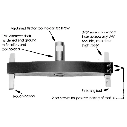
Fly Cutter Operation
Fly cutting is a technique wherein a single point tool is used which is revolved on a spindle. As the tool sweeps over the work piece, it cuts off material in order to generate flat surfaces with respect to the work piece. Unlike conventional multi-edge cutters, fly cutting makes use of only one edge. This mitigates the problem of chatter from the high tooth density of the cutter and assists in improving the quality of the surface finish. The spindle speed provides speed in cutting while the feed represents motion of the tool on the work surface. Due to the uncomplicated mechanism, maximum control and accuracy can be gained which makes it more useful in operations that require close tolerances. Tool Material, Cutting Grease Angle and Collant Spindle Speed are few aspects that need to be considered in order to extend cutter’s life.
Definition of Specific Technical Concepts
Cutting Speed
The term “cutting speed” implies the velocity at which a tool cuts through a work piece; this is conventionally expressed in SFPM (Surface Feet Per Minute) or meters per minute (SFM). This is a Very important variable as it helps with material removal, tool life and the freedom of getting a particular surface finish. For instance, when dealing with aluminum it might be necesary to apply a high speed of between 300 to 500 SFM in order to cut it, but when doing the same with titanium, it might not be possible to go any higher than 50 – 120 SFM.
Feed Rate
In a machine tool, the feed rate is the distance the workpiece is moved per unit of time, expressed for linear axes usually in inches per minutes (IPM) or millimeters per minute (mm/minute). The feed rate is of particular importance because it limits productivity, but also influences the surface quality of the final component. Increasing feedrates reduces machining time but it also reduces accuracy and quality of the surface created. When quality makes or breaks a component, feedrate is usually determined in connection with speed and the geometry of the tool.
Material of the Tool
The material of a cutting tool plays an important role in its performance as well as wear out. Their most common construction materials include high-speed steel (HSS), carbide and polycrystalline diamond (PCD). For example, carbide tools are very hard and heat resistant which is why they are used in high speed machining processes whereas, PCD tools are used for cutting abrasive materials e.g. composites and aluminum alloys.
Spindle Speed
Spindle speed refers to the speed of rotation of the cutting tool or workpiece expressed in terms of revolutions per minute (RPM). In machining operations, especially cutting operations, spindle speed is very important. Take for example a CNC machining spindle whose speeds may go beyond 10000 RPM for some fine cutting in a thin material as well as low speed for processes with a lot of material removal. Most modern CNC machines have a feature of dynamic spindle control that ensures optimum spindle speed is achieved based on the prevailing cutting conditions.
The angles in question, which include the cutting edge and clearances, modify the tool material behavior in use. Positive rake angles result in reduced force exertion in cutting which is suitable for softer materials unlike positive rake angles which offer more stability to the edge in harder materials. All these tools can be optimized within reasonable limits and can also be put within reach without her expertise and this can be useful.
Surface Finish and Its Measurement
Surface finish refers to the texture, roughness or smoothness of a generated surface, which is usually defined by parameters such as Ra (roughness average, arithmetic roughness). Within its limits, any applications that require strict minimum surface roughness including these visible ones, should not hesitate to achieve the best finishes. Finally, the use of advanced techniques, for instance, high speed fly cutting and micro-finish equipment is possible and the achievable finishes even below 0.2 microns Ra are able to reduce the post machining processing of surfaces.
Tool Wear and Tool Longevity
Wear of the tool mostly occurs when the edge gradually gets worn out because of the interaction of heat generated through friction and mechanical forces. Such particular patterns as flank wear or crater wear are observed to know how long a tool will last before replacements are due. Furthermore, current technologies include condition monitoring systems, which encapsulates an advanced mechanism embedded within modern tool holding equipment for maximum efficiency and metal cutting.
The advanced machining processes are possible because of the cumulative effect of these aspects: technical design.
Fly cutting remains popular for small, accurate, flat-surface -small components. Some users prefer it for the very reasons some dislike it, because sharp radius curves can be machined on large scale radius parts.
Precision Compared to Other Methods
Fly cutting offers superior precision with sub-micrometric form error and nanometric surface roughness, surpassing other methods in flexibility, cost-efficiency, and surface quality but with lower machining efficiency
| Key Point | Fly Cutting | Other Methods |
|---|---|---|
| Precision | Sub-micrometric | Varies |
| Surface Finish | Nanometric | Coarser |
| Flexibility | High | Moderate |
| Cost | Low | Higher |
| Efficiency | Low | Higher |
| Applications | Freeform, Nano | General |
| Tool Wear | Manageable | Varies |
| Cutting Speed | Constant | Variable |
| Material Types | Broad | Limited |
| Setup | Simple | Complex |
Advantages and Disadvantages of Fly Cutting
Pros of Fly Cutting
In addition to providing countless technical advantages over the older technologies, fly cutting is a necessary precision machining technique used in many industrial and research activities. Several of these pros of fly cutting are as follows:
Good Surface Finishes
With nanometric precision, fly cutting is capable of producing high quality surface finishing for situations where exceptionally smooth and even mirror finish surfaces are required, such as for optics or the production of semiconductors.
High Versatility
The great scope for use in various materials with different configurations, in particular non-linear or freeform geometries is also a major plus. This adaptability enables it to be used for special machining and complicated shapes which existing cutting techniques find impossible to make.
Economical benefits
The effective cost of tooling in fly cutting is less compared to most other advanced machining techniques. Therefore, it makes the manufacturing of parts with fine tolerance feasible for small quantities or prototypes.
Easy to Setup
The process of tool adjustment is basic in fly cutting and almost does not need any adjustments. This helps in reducing the time wasted during the machining operations and hence gives room to handling various projects sizes and workpieces quickly.
Low Consumption of Cutting Tools
The time taken for cutting the workpiece in fly cutting carries out with the help of the tool at a set constant speed. This means that the tool edges that do the cutting wear out evenly extending their useful life and lowering the associated costs of replacement.
Control Over Thickness and Dimensions is enhanced
The rates R emovable Materials to achieve the tight machining tolerances are met with satisfactory and, in some cases, even better. This ability makes fly cutting an enviable process in extreme precision industries such as aerospace, where each component must fit together like a jigsaw puzzle.
Thanks to enhanced equipment, fly cutting of contemporary forms with tolerances of up to ±0.5 µm is possible, making it an effective precision method. Research shows that fly cutting has flown smoothly in marketing ultra-high-precision freeform surfaces, even from such brittle materials as fused silica and ceramic. All of the above advantages prove that fly cutting is an important and useful technique in modern production.
Disadvantages and Limitations
Fly cutting offers exceptional surface finish and low tooling cost but is limited by low material removal rate, stringent setup, vibration sensitivity, and shallow depth of cut.
| Key Point | Advantages | Disadvantages |
|---|---|---|
| Finish | Mirror-like | – |
| Cost | Low tooling | – |
| Power | Low spindle need | – |
| Flexibility | Customizable | – |
| Vibration | Reduced | Sensitive |
| Setup | – | Stringent |
| Depth | – | Shallow |
| Rate | – | Low removal |
| Wear | – | Concentrated |
| Profiles | – | Limited |
Considerations for Implementation
- Machine Specifications: The machine which will be used for fly cutting should be very precise and sturdy so that required tight dimension is made possible in the workpiece. In addition, control of vibrations, as well as precise spindle, are vital requirements.
- Tooling: Select the right tool material and configuration for the particular workpiece material in order to maximize efficiency and lengthen the life of the tool.
- Materiality: Make sure that fly cutting is suitable for the material involved for the given task. Such materials like ceramics or very hard metal behave otherwise and may need special discretion when chosen as weld preparative material.
- Speed as well as Feed Rate Enhancement: Adjust the cutting speed and feed rate suitably and draw a line so as to hit the optimal point that has its priorities of accuracy good finish and turn out the most important aspects of the product.
- Coolant Application: Apply suitable cooling and lubrication methods to reducing heat generation and protect the workpiece or tool from distortion.
- Skill Level of the Operator: Train operators properly how to work with fly cutting processes so that safety and mistakes don’t happen.
- Cost Considerations: Assess if the expenditure on Fly cutting machine and its installation falls within the available funds and objectives of the undertaking.
- Inspection and Monitoring: Set exact methods of verification and checking that measure the tolerance and surface quality throughout the machining processes and after.
- Environmental Conditions: Carry out the required environmental conditioning to maintain the temperature and other critical environmental factors that would otherwise contribute to inaccuracy.
- Maintenance Routine: Plan for regular management of Fly cutting equipment in order to maintain the proper functionality and enhance durability.
Applications in Fiber Laser Machines
Industries Making Use of Fly cutting
- The aerospace industry: the manufacturing of some highly reliable parts, such as impellers and structural aerate.
- The automotive industry: the manufacture of high performance and high reliability components, such as the crankshaft, gearbox, etc.
- The semiconductor industry: relevant for fabricating the necessary flat topologies for wafers and processing of microelectronic applications.
- Medical devices: facilitates the creation of complex components and precise apparatuses for use in surgical applications and prosthetics.
- The optics industry: allows making surfaces of very high precision such as mirrors and lenses.
- Military: Applied in the fabrication of parts for weapons and other specialized military hardware.
- The electronics industry: aids in making frames and enclosures for components.
Examples of Various Design Applications
Aerospace Industry
In the aerospace industry, precision machining is an important aspect, particularly with regard to the manufacture of turbine blades, working elements of engines and structural assemblies since these are fabricated parts that require a higher level of tolerance and dimensions complimented by quality assurance dimensions. This restrictive requirement in the industry has been projected in a Vision 2030 and CDN 272 billion worth sector reported in the recent report, that there is a compound annual growth rate (CAGR) projected for the global aerospace precision machining at 6.9% between 2021-2028 as a result of new developments in commercial aircrafts, helicopters and military goods.
Medical Device Manufacturing
Minimally invasive surgical instruments and biocompatible implants are in high demand thereby culminating in substantial improvements in precision machining when it comes to the medical field. In fact, CNC machines produce titanium and stainless steel parts like orthopedic implants with proper tolerance up to even 10 microns. Marketed in the year 2022 at an estimated 536 billion USD worth medical device industry still demands more precision components.
Consumer Electronic Society
Moreover, the electronic parts of today’s society such as semiconductor packages, cooling devices and microconnectors are known to massively hinge on miniature precision machining. Since it is predicted that the global consumer electronics industry will go over $1 trillion in 2024, this calls for increasing demand for meticulously fabricated parts to enable miniaturization and improvement in functionality.
Car Industry
Engine blocks, components of the drivetrain and even complex systems like fuel injectors, are all manufactured by producers with high precision. In engine technology, electric vehicle (EV) propulsion demands low weight and perfectly machined components which effectively enhances the performance of the system while improving the apparent emissions. The value comes in “clean” terms whereas the EV market growth is projected to work in the range of 23.1 percent per year till 2030 thereby pointing out the inevitable dependence on precision manufacturing.
APPLICATIONS FOR THE DEFENSE FORCE
Important defensive equipment, including navigational systems, weather probe hardware, and munitions, are made of highly machined parts to prevent malfunctions. For Instance, parts intended for missiles might require less than 0.002 inches tolerance for proper function. Need of such tools has not decreased due to lopsided allocation by governments of almost $2.24 trillion for defense expenditures globally in the year 2022.
How Products Enable Application of Technologies
Among the fabricated products, which have been manufactured using precision machining technologies, include the following, illustrating the immense scope and diversity of fields to which they find application.
Parts Typical to the Air Transport System
- Turbo turbine blades
- Aerostructure fixtures
- Hydraulic fitments fuel size custom fit
Surgical Equipments
- Operating device
- BODY IMPLANT MODIFICATIONS
- Dental no endoscope screws
Motor Vehicle Components
- Engine parts
- Gearing
- Transmission cases
Military Hardware
- Missile control parts
- Parts of monitoring devices
- Connectors for protected vehicles
The images reinforce the essence of precision machining in the production of delicate, robust, and functional parts that are requisite for sophisticated industrial operations.
The many machining processes that can be employed in the shop floor include; fly cutting, boring, drilling, etc.
Future Trends in Fly Cutting for Fiber Laser Technology
Technological Progress
While the high tech processes of fly cutting fiber optic technologically is ongoing, the dynamic nature of technological progress flows rapidly, thereby showing an improvement of accuracy, efficiency, and capacity. The other most significant change will be observed in integrated AI control units, complete with live data recordings aimed at enhancing cutting accuracy and de minimizing waste. More so, the evolution of quality control of the beams and modulation of the transmissions of contemporary fiber based lasers allows cutting at very high speeds with greater accuracy fitting the customers’ demands such as those in aerospace and electronics. Latest techniques aim at blending focus on machining and fiber laser systems and more modern and advanced systems where accuracy and reach superiority are most effective. These changes are supposed to help the manufacturers to withstand the policy of the market in terms of acculturation in precision and economy but with the consciousness of the competition in the high level technologies.
Environmental and Corporate Social Responsibility
Environmental and corporate social responsibility has taken the forefront in every industry today as it aims at reducing the externalities of industry while boosting the efficiency of the operational system. In line with this, manufacturing plants have been using equipment that is energy saving and processes that are material-saving such as systems that operate within closed loops or those that enhance recycling. Moreover, solar energy and wind power systems are incorporated into plants to help minimize the use of dead plants or fossils as fuel. The use of sophisticated monitoring systems helps to compute the amount of energy used and the areas where performance is less satisfactory for purposes of adjustment. All these efforts go beyond simply complying with international environmental regulations but also enable curbing costs in the long run while promoting better business practices.
Challenges for the Future: What are the Predictions?
In my view, scaling the use of renewable energy while ensuring that it remains cost effective is among the main obstacles. Furthermore, the incorporation of advanced technologies into the existing infrastructure might also be difficult and costly to sustain the balance. Managing regulatory compliance and efficient scheduling of the changes to the supply chain might also be a challenge as we shift towards sustainability.
Reference Sources
- Laser Cutters – Texas Inventionworks (OLD) – A resource from the University of Texas providing insights into laser cutting technologies.
- Laser Cutter – Yale University – A document from Yale University discussing laser cutter operations and safety.
- LASER CUTTING: THE ULTIMATE GUIDE – fetlab.io – A comprehensive guide on laser cutting from the Rochester Institute of Technology.
- 3-Axis UV Laser Marker – MD-U1000 Series User’s Manual – A detailed manual from Arizona State University on laser marker systems.