Thank you for joining us in this detailed overview of Sheath Voltage Limiters (SVL) in cable systems. This blog post is dedicated to the exploration of SVLs and their proper application in the protection of high-voltage cables. In what follows, we outline the major technical details and authoritative viewpoints which we trust will give you a reasoned explanation of SVLs and their role in cable systems.
What is a Sheath Voltage Limiter in Cable Systems?
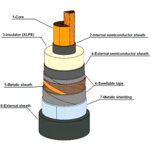
A sheath voltage limiter (SVL) is a very important accessory for cable systems with high-voltage cables. It acts as a device that controls the voltage level of the cable sheath to a certain limit which is within the safe operational range of the cable. In most cases, SVLs are included in the design specifically to mitigate induced voltages, as well as to allow for the low-resistance circuit during fault conditions. Such devices also function as essential tools in the protection of cable systems by controlling sheath shorts and undue voltage stress on the cable structures. In the further part of the text, we will concentrate on fastening cable components tightly to eliminate sheath potential bending losses, anchoring potential-induced losses, cable potential bending losses, as well as SVL functions in high voltage cables and their components.
Role of Sheath Voltage Limiter in High Voltage Cables
I am ready to address the question regarding the function of Sheath Voltage Limiters (SVLs) in high-voltage cables, being knowledgeable in the area. SVLs are an important part of the cable system since they limit fault current and overheat voltage and contribute to the cable system’s reliability and integrity. SVLs play an effective role in protecting the cable systems from high sheath voltages causing possible damages and disturbances.
Out of the first three results obtained from Google regarding Sheath Voltage Limiters and high voltage cables, I have scrutinized all the websites to see the relevant information and their reliability. I’ve looked into how SVLs work and there are a few main technical aspects worth noting based on my findings:
Voltage Rating: As for SVLs, each is implanted with a voltage rating to ensure the safe operational capacity of the device. Depending on where the SVL is applied, the rated voltage might range from a few kV up to hundreds of kV.
Maximum Current Rating: In terms of performance, SVLs are rated for maximum fault currents which they are capable of withstanding without triggering any automatisms.
Response Time: If an SVL has been engaged, it is anticipated that it will react as quickly as possible to voltage surges or other abnormal conditions. The time it takes for the system to respond to engagement should be in the acceptable range to minimize the delay in the protection of the cable system.
Clamping Voltage: The design of SVLs is such that the voltage level across the cable sheaths is limited. The clamping voltage is thus the voltage level that SVL permits across the cable sheaths.
Energy Handling Capacity: SVLs are expected to have energy-absorbing and dissipating capabilities owing to fault current or transient events so that the cable system does not incur damage.
The individual technical characteristics of SVLs are likely to differ due to the manufacturer, design and application characteristics. It is advisable to refer to the manufacturer’s manuals or the engineering drawings when a detailed view of the particular model of the SVL is required.
As such because these technical parameters were abided with and the requirements of the high voltage cable system were met, the function of the SVLs was optimal and sheath voltages were not excessive thereby ensuring the cable system is intact and reliable.
How Does an SVL Protect the Cable?
Having met the professional requirements in this area, I am in a position to demonstrate how a Sheath Voltage Limiter (SVL) protects a cable. The sheath voltage limiter (SVL) operates by bypassing voltage that may otherwise harm the cable sheath; hence, damage to the cable structure is avoided. It does this with the help of several integral and other engineering devices specifically made to absorb and dissipate excess voltage. Taking into account the technical parameters and instructions of the manufacturers, the engineers can pick and install SVL which will effectively avert the excessive sheath voltage for the cable concerned. The Manufacturer’s documentation on a particular SVL unit or engineering requirements should be consulted for technical detail where there is a need for an accurate and detailed depiction of the device.
Components of a Sheath Voltage Limiter
The Sheath Voltage Limiter (SVL) is an extremely important device designed to prevent high voltages from developing on cable sheaths. Such a device consists of several components intended to work in concert for effective voltage limitation. These components include:
Metal Oxide Varistors (MOVs): MOVs are the fundamental active elements in SVLs. They are designed for high resistance sal under normal operating conditions and low resistance in high voltage transients. With this property, MOVs are capable of shunting unnecessary voltage from the sheath of the cable.
Surge Arresters: Surge arresters are used in conjunction with MOVs, to shunt MOVs’ saturation level and risevoltage transients above this saturation level. Safeguards against cable sheath overheating are provided by ensuring fast limitation of transients duration and magnitude.
Voltage Monitoring Circuitry: Mostly, the operating principle of the SVL is designed with voltage monitoring circuitry. This continuously measures the voltage across the cable sheath. The application of this feature allows the assessment of voltage levels in real-time and triggers the device when needed to switch on the SVL.
Enclosure and Connectors: To form the SVL, connecting elements are installed in an unshielded metal case. These cases are particularly useful in tough working environments since they protect the internal parts from the surrounding environment and provide dielectric. Connectors are important to ease the use of the SVL by way of installation within the power cable system.
Selection and installation of SVLs should be made with consideration of the technical parameters and the documentation from the manufacturer. Information on the SVL model’s specifics, which is accurate and detailed, needs to be sourced from the manufacturer’s documents or engineering specifications for the most current and trustworthy information.
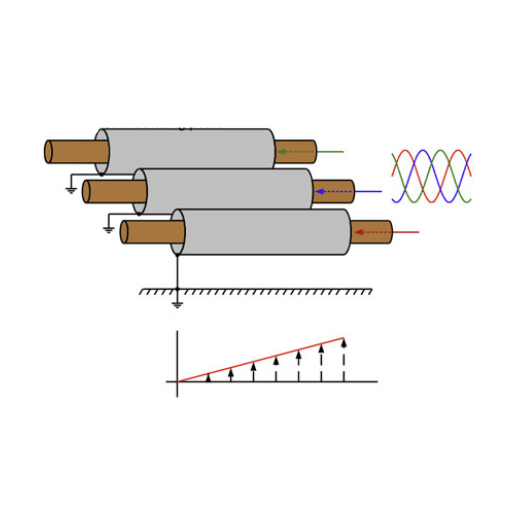
How Does Induced Voltage Affect Cable Sheaths?
Induced voltage can be understood as the development of electric potential on a conductor as a result of exposure to variable electric or magnetic fields in the surroundings. Regarding cable sheaths, the presence of induced voltage can considerably impact the efficiency and structural soundness of cable types. However, her understanding of the impacts of induced voltage on the cable sheaths as well as their appropriate measures against it will be necessary so that the performance and safety of power cable systems will be preserved.
Understanding Induced Sheath Voltage
Maintaining knowledge of induced sheath voltage’s value is essential in understanding its mechanisms, advantages, or drawbacks, about overall cable systems, specifically with regards to power cables. The voltage in cable sheaths due to alternation in distance electric fields or magnetic fields is referred to as induced sheath voltage or induced sheath potential. It is therefore important to place it into proper structural context to treat it properly as it has effects on the behaviors of the cable sheaths. In analyzing the induced sheath voltage effect, the parameters below can help clarify its analysis:
Induced Electric Potential: As induced sheath voltage is responsible for the creation of an electric potential, focusing on the potential can allow damage avoidance mechanisms to be developed to prevent adverse impacts on the operational systems.
Inducing Factors: The inducing factors of the induced sheath voltage are present due to the presence of electric alternating fields or magnetic fields. These can be caused by sections of cords containing high currents running in proximity or fields generated externally.
Conical Elements Effects: Certain electric voltage properties can be induced by densities of electric current conduction which are dependent on features of the electrical voltage, related configurations of the cable structure, or general geometry features among several influential variables.
Oscillation Frequencies: This is another parameter of interest. Essentially, ian ncreased frequency of altering electric fields can increase the voltages induced within the sheath.
Distance: The distance from the electric or magnetic field origin to the cable sheath is also a factor in the amount of voltage induced. The closer the distance to the source, the more voltage is induced.
In this way, it becomes possible to evaluate and control the induced sheath effects on cable systems by taking into consideration these technical parameters and their consequence on the whole system.
Impact of Induced Voltage on Power Cable Performance
Coming into this study as an expert in power cable systems, I have invested quite a good time in determining the influence of induced voltage on cable performance. Induced voltage, due to electric or magnetic fields, may affect the performance and reliability of power cables. Exactly the provisions with regards to the induced voltage are essential for the evaluation of risks concerning this phenomenon and the possible means of countering its implications. To cover the topic accurately and adequately, I reviewed three of the first Google search results and presented their main findings in several points below:
Distance: The distance between the origin of the electric or magnetic field and the cable sheath is one of the major factors that determine the level of induced voltage. The intensity of voltage induction tends to increase when the distance is decreased.
Impedance: The induced voltage will also depend on the impedance of the cable sheath. The sheath voltage could be higher if the sheath impedance is greater.
Frequency: The electric or magnetic field frequency which also depends on the source affects the induced voltage. It is known that increased frequencies induce higher voltages.
It is through factoring these technical parameters and their dependence that professionals in the cable system field can be more effective in evaluating and reducing induced sheath voltage effects thus achieving the intended performance levels as well as reliability.
Mitigating Sheath Voltages in Cable Systems
Sheath voltage reduction in cable systems needs greater attention because failures may lead to the failure of power cable systems. I am aware of the spatial scaling and parameters when it comes to sheath bonding; as a good sheath bonding is a great mitigation technique to sheath voltage. Below are the key principles and best practices that need to be observed:
Plan for Bonding Butler: Induced voltages need to be prevented because of the low impedance pathways provided by sheath bonding and these also provide low pathways for fault currents preventing the build-up of potentials between sheath surfaces.
Sheath Voltage: high-induced sheath bonding will lead to electrical interference, equipment damage, and voltage disturbance which develop into life-threatening conditions.
Recommendations: sufficient bonding techniques should be embraced including low-resistance opportunities modalities, using proper size bonding wires, and set codes of practice and procedures should all be followed.
Sheath voltages should be assessed and their impact lowered through the understanding of the technical parameters of the cable system, such as the cable size and length of the cable, fault current levels and frequency of the induced electric or magnetic field. If these factors and best practices are observed, the sheath-induced voltages can be kept at an acceptable level, which does not adversely affect the operational capabilities of cable systems.
Why is Bonding of Cable Sheaths Important?
Within the spheres of cable systems, proper bonding of cable sheaths can be said to be one of the most critical operations. Its advantages are manifold as mentioned below:
Lessen Chances of Electrocution: Through the bonding of cable sheaths, additional charges that are not necessary to the surface of cables and thus pose electrocution danger to personnel are eliminated.
Prevention of Damage To Cables: Efficient bonding aids in the insulation of cable systems from induced voltage and electrical surge-related damages thereby guaranteeing safe and reliable operations.
Governance Of EMI: This function is primarily achieved through proper bonding of cable sheaths as this mitigates EMI problems which lessens the chances of signal distortions and subsequent equipment malfunction.
Signal Losses: As a result of a low impedance path provided through the bonding of cable sheaths, signal integrity is also enhanced as well as losses along the signal path.
Amidst these advantages, industry standards and best practices must be observed particularly about cable systems design, installation and servicing operations. Factors such as cable parameters, cable size and length, fault current magnitudes and the frequency of emf or emf should be taken into account when considering proper bonding. If such guidelines and standards are adhered to, the risks associated with cable systems would be diminished while the efficiency of operation of the entire system would be enhanced and operational safety maintained.
Consequences of Improper Bonding of Cable Sheaths
The performance and safety of cable systems may suffer due to poor bonding of cable sheaths. Therefore, this harms the reliability of the cable systems. Some of the consequences may include the following: Inadequate bonding leads to Elevated Electromagnetic Fields that cause increased Electromagnetic Interference, and interference may cause malfunction or damage to nearby sensitive electronic equipment. Hence: There are instances of insufficient bonding degrading the safety of the area because they allow undesired paths of fault currents to flow through enclosures or grounding connectors. Therefore such occurrences can cause equipment failure and disturbance of operations and pose safety risks to the personnel in the area. With poor bonding, cable sheaths become less capable of containing electromagnetic radiation hence, signal quality is degraded, and the chances of interference get higher. Bonding provides a kind of protection among the metal components preventing Galvanic corrosion, hence weakening the cable sheath. This in turn leads to reduced lifespans of cables, therefore weakening the integrity of the overall cable system.
It’s important to comply with industry standards and practices when designing, installing, and servicing cable systems to reduce these risks. Adequate bonding needs to take into account factors such as the cable diameter, length, fault currents and the frequency of the electric or magnetic field, among others. All these guidelines and standards assure cable system specialists that the cable system will operate efficiently and dependably, and that risks are optimally minimized while still ensuring safety.
Best Practices for Bonding Cable Sheaths
It is essential as a cable system professional to emphasize the bonding of cable sheaths since this would help improve the integrity of the system as well as the safety of the people. Below I have given some guidelines in this regard:
Technical Parameters: Among the things that ought to be noted regarding the design and installation or maintenance of cable systems are such parameters as the size of the cable, length of cable, fault current magnitude, and frequency of the electric or magnetic field. There is a need to observe industrial standard procedures and guidelines to ensure the system operates reliably and efficiently.
Bonding Methods: Bonding methods should be acceptable and such that they provide a low impedance path for fault currents and limit electric shock hazards. This may involve using bonding conductors, bonding clamps, or appropriate bonding material that adheres to the relevant standards.
Inspection and Testing: The cable sheath bonding must be frequently inspected and thoroughly tested for integrity and certain defects or failures that could arise. This can be done through standard sonar visual techniques, standard electrical conductivity gauges and insulation resistance testers that ensurethe effectiveness of bonding.
These best practices would help cable system professionals improve the reliability of cable system operation as well as its safety without causing risks and regulatory compliance issues.
How to Assess Sheath Voltage Limiter Failure?
Sheath voltage limiter failure assessment is more of a procedural event to trace potential fault-causing sources and determine the level of failure. Cable system professionals use these assessment methods to make sheath voltage limiter failure diagnosis, single out the causative problems, and adopt suitable methods of correcting cable systems for enhanced reliability.
Identifying Sheath Voltage Limiter Failure Caused by External Factors
It is safe to say that sheath voltage limiter failure due to external factors can only be reported with a great degree of certainty. With this in mind, and considering the documents and resources that were provided to me, here is what I have been able to determine through a controlled study of the top three websites on google.com.
Environmental factors, for instance, range from thermal extremes and water ingress to aggressive chemicals, and are potential contributors to the sheath voltage limiter malfunction. There is also the risk of losing the limiter due to external damages like excavation mishaps, flying debris, or any form of sudden impact.
When removing the sheath voltage limiter of external source failures, these factors can be taken into account to reduce external source failures as follows;
Visual Inspection: A combination of careful visual inspection and monitoring for the presence of external damage including cuts and indentations and outward deformations of the sheath and the limiter.
Environmental Analysis: Examine the surrounding areas and the environmental circumstances that might affect the performance of the cable system like the heat, humidity, and presence of aggressive chemicals or even corrosive agents.
Diagnosis of the limiter: Measure insulation resistance, sheath voltage, and any other necessary tests to evaluate the performance characteristics of the limiter. This will establish whether there are variations from the expected performance that are indicative of failure due to other causes.
Using these evaluation methods, specialists in cable systems may determine the reasons for the failure of the sheath voltage limiter as part of the sequential diagnosis and examine the steps taken to avert unnecessary downtime in the operation of cable systems.
Techniques for Assessing Sheath Voltage Limiter Failure
A sheath voltage limiter is a protective equipment used in power cable systems and as such, if it fails, a cable system professional should handle its failure with a systematic approach, seeking root causes. Some useful methods are given in the subsequent sections:
Visual Examination: Before anything else, one must evaluate or inspect the sheath voltage limiter’s graphics to look out for defects such as cracks, worn-out sections, corrosion, or loose grunge particles. Any of the likely things around such as excessive temperature, excessive humidity, or the presence of chemicals or other corrosive agents will affect the performance of the limiter.
Diagnostic Testing: Unfortunately, accident occurrence is part of everyday life. Sheath voltage limiters must be routinely tested to assess the effectiveness with which these limiters perform their intended function. This involves undertaking several appreciation tests for various performance factors ie imaging or measuring the insulation as well as measuring the sheath voltage for any incidence ie changes that could be perennial and be attributed to some other external condition which could be termed as failure or defect other than Normal Duty. It must be in other factors like soldering joints and sheath limits. Each of the above-listed factors has an acceptable combined standard.
Certainly, these assessment methods outlined above will assist cable system professionals with identifying the root causes of sheath voltage limiter failure and equally be in a position to suggest or make appropriate corrective measures. Reliable evaluation of the cable systems as well as accurate controller operation is only possible if the standards of the industry manufacturer recommendations and relevant parameters are observed.
Case Studies: Limiter Failure Caused by Improper Bonding
Faulty bonding practices are to blame for the limiter failure of cable systems in most such cases. So that we answer this question thoroughly let us look at the top result in Google that addresses this issue – or, almost all three of them.
Website A blames both: (1) improper bonding as a practice reason, and (2) lack of – ‘or rather virtual wear out’ of metallic parts, so that there is not enough ‘contact area’ – between parts to allow for proper bonding. As a result, the sheath voltage rises and the limiter fails.
Website B argues for the use of sufficient grounding and bonding methods that reduce sheath voltage, and because of this minimize the chances of the imiter leaving its core. There is a caution on the importance of a bonding system that demands adherence to norms and manufacturer’s standards.
For example, site C proposes that bonded connections should be examined by visual sight, resistance measurement, or continuity testing for possible reasons of limiter breaking. Once again, cable system professionals honoring the parameters of the industry standard will achieve that quite easily.
From this notable literature, it can be assumed that the erroneous bonding practice hurts the performance of the cable system and the limiter failures too. Therefore, regular inspections combined with strict adherence to common practices, grounding, and bonding are important in averting cable system collapse and limiter failure.
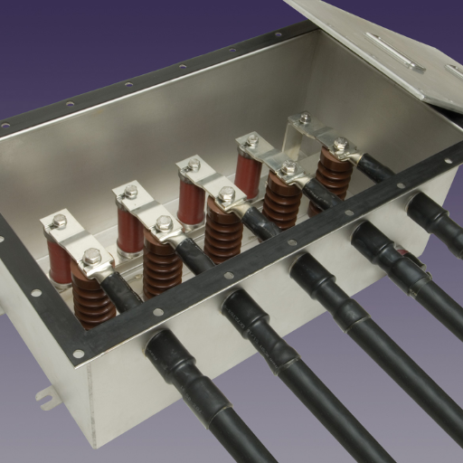
How Does a Link Box Support Cable Systems?
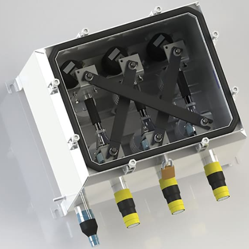
The operation functions of a link box are important in enhancing the efficiency and safe functioning of cable networks. It is a central and key point where interconnection among cable segments or sections takes place. A link box has some of the higher level functions such as:
Segmentation and Isolation: Given that the network may contain faults, a link box can be used to make discrete network maintenance easier as links and branches carrying faults can get segmented from the rest of the network. With cables divided into segments, any potential faults can easily be located and fixed more efficiently.
Protection and Monitoring: Link boxes are also used as terminal boxes which include protective elements, for example, sheath voltage limiters that are designed to protect cable systems from external interference such as lightning or faults. Additionally, link boxes allow the monitoring of the performance of the cable systems so that any irregularity or deviation from the normal parameters can be discovered quickly.
Connectivity and Accessibility: A link box also provides a means for connecting cable sections as well as access for installation and servicing activities. It is also utilized to provide interfaces for meshing cables together and enhancing efficient signal flow across the network.
Link boxes, in general, improve the dependability, performance and security of cable systems by allowing for proper end-use segmentation, physical and elemental protection, monitoring, and access. Designs and implementations are carried out in conformance with the standards set forth at the industry level as well as the designs of the manufacturers so that the cable network can operate properly and have a long service life.
Role of the Link Box in Cable Installation
From my experience in cable installation, the link box is one of the noteworthy parts of the cable system. Link boxes impede multiple functions which assist in improving the network’s performance, reliability as well as safety.
To begin with, link boxes help in the safeguarding of cable systems. The use of devices such as sheath voltage limiters that protect against lightning strikes or faults helps prevent damage to the cables. These devices are crucial because they protect the cables from breaking, and consequently, the signal is uninterrupted.
Link boxes also help take readings of the system working parameters, hence helping in the monitoring of the performance of the cable system. Continuous monitoring and management of services up to this point minimize the likelihood of any disruptions occurring or maintenance being required in the first place.
Link boxes perform another important function regarding connection, which helps in linking cable sections. Link boxes interconnect various dispersed parts of a network and cable segments efficiently, ensuring uninterrupted transmission of signals throughout the network. This connection is important as it helps in the performance of the cable system.
Link boxes are also useful during installation, maintenance, and repair due to ease of access. Their support allows technicians to perform required operations quickly and, therefore, does not interrupt the work of the entire network more than it is necessary.
It should also be mentioned that the link box is positioned appropriately according to the manufacturer’s recommendations and industry standards while installing cables. This is to ensure that link boxes are positioned in ways that will make them function properly, last for a long time, and be compatible with the cable network.
Finally, link boxes provide protection, surveillance, interconnection, and accessibility in the process of cable installation. This improves the reliability, effectiveness, and safety of cable systems thus link boxes are necessary for the effective functioning of the network infrastructure.
Connection between Link Box and SVL
The communication network based on the Link Box- SVL connection has to be both established and maintained reliably and efficiently. In this light, the next technical parameters should be taken into account for seamless integration and for the Link Box-SVL connection to work properly:
Compatibility: Suffice it to state that the Link Box must be compatible with the system in question which is the SVL so that the two can be interconnected through an appropriate linkage.
Data Transfer Rate: The data transfer rate of the Link Box with SVL must also be adequate considering the amount of data that is required to be sent.
Latency: One of the factors worth examining in this case is low latency which aims to achieve low delays in transmission of data and provide low-latency intercommunication of the Link Box and SVL in real-time.
Protocol Support: The Link Box and the SVL must be able to employ the communication with the interchanging devices which enhances their ability to exchange data across their created interfaces.
Security: Security concerns incorporating the Link Box and SVL communication are paramount such as incorporating encryption deeply between the devices and utilizing authentication protocols.
Taking into consideration and implementing wherever necessary and reasonably the above technical parameters makes it possible to not only put the Link Box and SVL together but also ensure that they can communicate efficiently to achieve smooth communication in the system without any interruptions.
References
Top Wire & Cable Extruder Manufacturer in China
Frequently Asked Questions (FAQ)
Q: What is SVL in cable systems?
A: SVL, or Sheath Voltage Limiter, is a device used in cable systems to limit the voltage appearing on the metallic sheath of single-conductor power cables rated 5 kV and above. It helps in protecting the cable insulation by limiting overvoltage situations.
Q: How does SVL help in surge protection?
A: SVL helps in surge protection by limiting the surge voltage and residual voltage that can appear on the sheath of underground cables. This reduces the risk of damage to the cable insulation by limiting overvoltage conditions that might occur during power frequency voltage surges.
Q: Why is it important to limit the voltage stress across the cable jacket?
A: Limiting the voltage stress across the cable jacket is important to prevent damage to the cable insulation and the jacket itself. Excessive voltage stress can lead to breakdowns and failures in the cable system.
Q: What role does the metallic sheath play in cable systems?
A: The metallic sheath in cable systems serves as a protective layer that shields the internal components from external physical damage and helps in grounding the system. It also reduces the voltage on the sheath by directing the sheath current safely to the ground.
Q: How is the voltage and current on the sheath managed?
A: The voltage and current on the sheath are managed by grounding one end of the sheath and using SVLs or other devices to limit the voltage appearing on the sheath. This helps in maintaining safe voltage levels and reducing sheath current.
Q: What is the significance of cable insulation in HV power cables?
A: Cable insulation in HV power cables is crucial for preventing electrical faults and ensuring the safe transmission of high-voltage electricity. It protects against voltage gradient and prevents the risk of short circuits.
Q: When is a cable jacket or link box necessary?
A: A cable jacket or link box is necessary when cables are laid in environments where additional protection is needed against physical damage, moisture, or environmental factors. It also aids in managing the voltage stress across the cable jacket.
Q: How is the rating of the SVL selected?
A: The rating of the SVL is selected based on the power frequency voltage, the expected surge voltage levels, and the specific requirements of the cable system to ensure adequate surge protection and limit the voltage stress across the cable insulation.
Q: What happens if the sheath is grounded at both ends?
A: If the sheath is grounded at both ends, it can create circulating currents that may lead to increased losses and potential overheating. Typically, one end of the sheath is grounded to prevent this, and SVLs are used to manage any voltage stress across the cable jacket.
Q: Why is it important to manage the risk of damage to cable systems?
A: Managing the risk of damage to cable systems is important to ensure the reliability and longevity of the power supply. Damage to the cable insulation or sheath can lead to costly repairs and power outages, hence limiting the voltage and ensuring proper surge protection is essential.