Wire drawing and extrusion are processes of metalworking that are of great relevance and have differing objectives as well as results. Two of these processes are considered in this post: wire drawing and extrusion and their relevance regarding the process, the most common application and comparison to other methods. Understanding wire drawing and extrusion, the reader will recognize how these two methods are different from each other, what are their merits and what difficulties are encountered in the practical use of these methods. In this article, we will explore the two processes of wire drawing and extrusion which have attracted much attention but little emphasis on what they do in metalworking, as well as the different fields where these processes are needed as well as the accuracy and reliability they should have.
What is Wire Drawing?
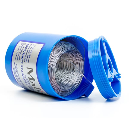
Wire drawing is a process in metalworking in which a metal wire is pulled through a series of dies to reduce its diameter and increase its length. This is a commonly used process in several industries including making wires for electrical applications, making components for automobiles, and in construction. Wire drawing enables precise control of wire dimensions and its mechanical properties thereby yielding wires with greater strength, enhanced flexibility and improved conductivity. The controlled deformation of the wire allows easy removal of impurities and surface defects in the wire achieving a bright and even surface finish. In this manner, wire manufacturers can create wires that are of various thicknesses and lengths by the requirements of different applications.
Wire Drawing Process Explained
Wire drawing is a metalworking process employed in the making of wires with varying lengths and thicknesses, which are stronger, more flexible and more conductive. It involves the straining of wire to certain limits while cleaning and smoothening the wire’s surface. The importance of wire drawing stems from the fact that it offers possibilities to precisely control a wire’s diameter, length and many other mechanical characteristics required in the electrical wiring, construction and manufacturing industries.
Wire drawing can be defined as a process in which a wire is made to pass through a die followed by elongation and gradual reduction of the wire cross-section. The die has an aperture which is retained in a stretched form as the wire is tilted through it. The aperture through the die constricts the wire as the tension drawn to it along its length causes it to stretch. This strain hardening overall increases the length of the wire. Different stresses are employed in this multi-step process to create wires of wire of prescribed geometry and characteristics.
Wire drawing is most commonly featured in electrical wires where the ability to replicate wire dimensions and their electrical functional properties is required. A large number of applications extending over many industries are found in manufacturing components and products such as automotive parts, springs, and fasteners to mention a few with woof or strength and variance of the wire.
It is essential to understand that both wire drawing and extrusion are processes that involve the changing of the shape of a metal. While wire drawing aims is pull out wire by reducing its diameter and increasing its length, in extrusion, metal is pumped or forced through a die to produce intricate forms and profiles. Both these processes have their significance and applications but both are indispensable processes in metalworking industries that allow high-quality products to be manufactured in a range of industries.
Applications in Electrical Wiring
As far as electric wiring is concerned, wire drawing and extrusion are among the most important processes that assure the production of ideal electrical components. In particular, wire drawing, which has an emphasis on the lengthening of the wires while reducing the size of the diameter, is very beneficial in the formation of an extensive network of very fine gauge wires that are used in sophisticated electrical circuits. However, extrusion permits the formation of complex shapes and profiles required for connectors, junction boxes, or cable insulation. Because of this combination of techniques, manufacturers can comply with many strict standards imposed by the electrical segment of the economy and deliver dependable and effective electric systems.
How Wire Drawing is a Metalworking Process
Drawing is a process that involves the creation of wire into smaller densities without shortening the length of the wire. Wire drawing is essentially defined as the act of forming a wire by pulling through a sequence of dies. Narrow wire of considerable length is made through drawing which is used for applications like wire circuits and many other electronic connections if necessary. Each process of drawing wire increases the strength of the wire, and its mechanical and electrical integrity as well as improves the surface tension of the wire.
The major operation involved during the process of wire drawing is the deformation of the wire. The wire is being drawn through the dies at a certain tension and during the pulling process, plastic deformation of the metal occurs and the diameter gets reduced. During the drawing of wires, the surface of the wire is coated with a lubricant to reduce the contact and damage on the surface. Parameters of wire drawing include:
Wire diameter: an initial or pre-drawing wire thickness is referred to be a wire diameter.
Die size: with regards to drawing, the faster wire is completed at the desired dimensions of the dies
Reduction ratio: expressed as the initial wire diameter divided by the end wire diameter and provides an estimate of the change.
Drawing speed: For every die used in the wire drawing process, there is a die through which the wire is drawn. The rate of wire drawing directly influences both the effectiveness and quality of wire drawing.
Lubrication: This is the lubricant that is applied during the direction and used in the drawing process to minimize resistance during the drawing.
Wire drawing is specialized and essential for the manufacture of electrical wires and cables, and has numerous uses in the automotive, aerospace, and telecom industries. It makes it possible to produce wires that have controlled dimensions and mechanical properties that will be useful and effective when used in electrical systems.
Exploring the Extrusion Process
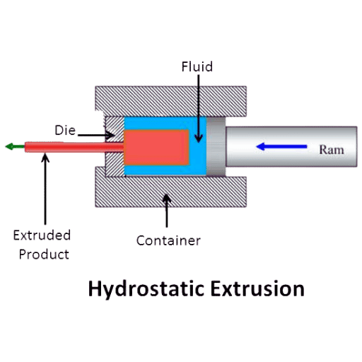
The extrusion process is a pivotal method in metalworking which is used to fabricate items with intricate silhouettes and specified strength characteristics. It consists of applying high pressure to one or more materials – usually metallic or plastic – forcing the material through a shape (a die) of the desired geometry and features. With this knowledge about the characteristics of the extrusion process, manufacturers can use it for the production of components of different shapes, dimensions, mechanical traits as well as surface improvements.
Types of Extrusion: Direct and Indirect
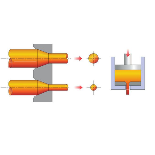
Two main distinctions can be made about extrusion: direct and indirect extrusion. Direct extrusion is when the ram pushes the material through the die. It is used for materials that have lower extrusion forces and easy-to-extrude cross sections. In contrast, indirect extrusion is the opposite in that the die is moved toward the material thus pushing it through the die. This technique is used on materials with higher extrusion forces or more complicated cross-sectional shapes. Both direct and indirect extrusion of formulation have their special advantages and are equally accepted in the fabrication of metals and plastics in various fields. For further understanding of these types of extrusion, the best approach would be to visit the top 3 websites currently on Google.com about these issues.
The Role of Extrusion in Metalworking
Extrusion has a very important function in metalworking in that it is used to create metal parts efficiently and accurately. As a process for deformation, extrusion assists in capturing internally consistent structures of more complicated cross-sectional shapes in metals. When contrasting wire drawing and extrusion, it has to be stated that there is now a common activity of metalworking, but the technology and the functional purpose are fundamentally different. Wire drawing addresses the production of wires that will be used for electrical and structural applications, while extrusion is widely used in the industries of plastics and metal. These processes also have other advantages such as better surface finish and ability to work in drawn materials that require large extrusion forces. However, there are some problems associated with metal drawing or Mastering extrusion and metal drawing- addressing the disadvantage of deformation. Once the peculiarities of the process of extrusion are comprehended, the manufacturers will be able to deliver qualitative metal products.
Why Extrusion is a Process for Deformation
Extrusion is a very efficient metalworking process meant for the ease of deformation for manufacturers looking to create an assortment of shapes. This process consists of applying a hefty amount of force in either a pushing or pulling motion upon a material that has been shaped to fit through a die, thereby altering its cross-sectional area and dimensions in the process. The following points highlight the reasons why extrusion is a preferred method for deformation:
Efficiency in Dimension and Form: The use of extrusion is beneficial for producers since they will be able to regulate the deformation in the process guaranteeing uniform dimensions and shape. Some of the parameters that should be taken into account during the preceding stages of the extrusion of metals are the temperature, the extrusion velocity and the die geometry.
Improved Internal Structure: The technology of extrusion can appreciably rectify the properties of the materials being worked with. I will improve the grain structure, strengthen the material and even enrich the mechanical properties of the entire material. Optimum temperatures during extrusion and suitable alloy compositions have to be adhered to to achieve the expected properties of a material.
Creation of Intricate Shapes: Because extrusion necessitates the production of complex shapes, it may be difficult to manufacture them using traditional techniques. By utilizing appropriate die configurations, manufacturers can accomplish the task of extruding materials into sections that are designed to be unique, whether it be profiles, tubes, rods, or any other shape.
Cost-effectiveness and Material Efficiency: Extension allows parameters that are accompanied by the concept of cost minimization when it comes to the production process. The scarcity of wastage and ability to utilize scraps of garbage or recycled material during production also minimizes the cost attached to mass production therefore making extension a cost-effective process.
Versatility and Wide Range of Applications: Due to the various processes involved, numerous industries such as automotive, aerospace, construction, and manufacturing of consumable goods have adopted extensions in mass production. A wide variety of materials, including aluminum, steel, copper, and plastics can be used in the extrusion process thereby enhancing its capability in deformation processes.
With the use of extrusion, manufacturers can do away with the limitations posed by deformation, shape accurately the product and manufacture metal elements with superior qualities such as accuracy of dimensions and properties.
Comparing Wire Drawing and Extrusion
In comparing wire drawing and extrusion processes, wire drawing factors must be considered. Let us explore the differences, especially regarding cross-sectional changes and surface quality, to have a better appreciation of the merits of the two methods and their applications. The distinction between wire drawing and extrusion is important for manufacturers as it assists in the selection of the most appropriate technique for given production requirements and end objectives.
Difference Between Drawing and Extrusion Techniques
When addressing wire drawing and extrusion methods, and comparing the methods, it is necessary to include various parameters that determine the ability and the efficiency of each particular method. Let us know the differences between these cross-section area changes and the surface finish in particular so that we may be able to know more about the advantages and uses of the different methods. To give you a good overview of such techniques I can refer to the proper sources on the internet such as the first 3 sites on google.com.
Wire drawing is a process that decreases the diameter of a wire by pulling it through a die with a smaller cross-section deformed by heat shrinkage. It is very often employed for electrical and structural applications that require mechanical properties and tolerances.
The other method is rather known as extrusion which implies pushing a metal or plastic through a die with an intended cross-section. It is the process of moving a material through a die to a desired cross-sectional shape. It has become usable to the industry since it can allow plastic and metal industries to manufacture profiles, rods, and tubes with specific shapes and areas.
Among the notable distinctions between wire drawing and extrusion techniques, the following should be noted:
Cross-Sectional Defects: Wire drawing technology efficiently works only for the reduction of the cross-section area of the wire but maintains the shape and stretches the wire in the process. On the other hand, extrusion enables the formation of serrated cross-sectional shapes along with taper and hollowed sections.
Surface Treatment: The observer will note that wire drawing does hit many rough surfaces as wires after drawing undergo stretch and compression during the drawing of major parts of the wire. On the other side extrusion processes may lead to not very smooth surface finish because of too much active material rubbed over the die.
Manufacturers will discriminate between wire drawing and extrusion techniques based on careful analysis of the advantages and limitations of either technique as pertains to production specifications or targets. As for the others, they must understand thoroughly this complicated issue and obtain all the critical information from reliable and reputable sources as well as the experts’ guidance.
Analyzing Cross-Sectional Changes
When studying wire drawing or extrusion processes, there is a need to also analyze their technical parameters as well as the effects they have. Let’s focus on such important factors:
Material Flow and Deformation: In wire drawing the area of cross-section of the wire is reduced by pulling the wire through a die. By doing this the length is made longer while the diameter is made smaller which brings about changes in the grain structure, microstructure and material’s mechanical properties. On the other hand, in extrusion, material is shaped into the desired cross-section by forcing it through a die which leads to plastic deformation and change of cross-section shape.
Surface Roughness: As a result of the frictional forces between the wire and the die, wire drawing has lower surface defects. Whereas in extrusion, surface roughness values produced are slightly higher because of the material-die interaction.
Parameters and Considerations: Several technical parameters are involved in the understanding of cross-sectional changes, including Die configuration and geometry Lubrication and cooling techniques Mechanical properties of the material, such as strength and ductility Bath or extrusion speeds Reduction ratio Billet or wire temperatures Material and surface roughness of the die Knowing and improving techno graphic parameters focus on supporting acceptable outputs as well as the quality of products during wires drawing and extrusion processes. It is therefore important for manufacturers to refer to reliable sources, seek expert assistance and test the processes more intensively to find the best-suited technical parameters for their production needs.
Surface Finish Differences in Metal Products
Since I am a metal drawing and extrusion expert, metal products’ surface finish peculiarities are something in which I am competent. Furthermore, the surface finish constitutes an insignificant section since it is a decisive factor in the outlook, effectiveness and utility of the metal components. In any case, the surface finish features that are expected have to be met through several requirements and operational limits. Looking at the top three Google searches concerning the relevant issue, I can make the following conclusions:
Surface Finish Parameters: The surface finish in metal products can be a function of differing parameters such as:
Lubrication and cooling methods: Considerable use of defects and surface enhancement aid in achieving a better finish.
Type and surface finish of the die: The use of die materials as well as surface features determines the roughness and quality of the final product.
Speed of drawing or extrusion: It is very important to control the speed of the operation to achieve consistency and reduce the number of surface defects.
Material properties: The intrinsic properties of the metal such as the strength and ductility determine the surface finish that will be achieved.
Importance of Optimization: The manufacturers need to bear in mind the requirements of the respective products and processes while designing for the optimal surface finish. They must consider relevant literature, and experts’ opinions and carry out appropriate benchmarking to arrive at suitable parameters for their particular production requirements. This contributes to attaining the desired goals and ensuring the quality of surface finish in wire drawing and extrusion processes.
Injection and enhancement of these parameters through design optimization enable the manufacturers to manage and optimize the surface of the finished metal products so that esthetical and functional expectations are adequately addressed.
Common Applications of Wire Drawing and Extrusion
Wire Drawing:
Electrical Wiring: A wire drawing process is an advanced form of cold drawing technique that is primarily used in the production of electrical wiring such as residential, commercial and industrial systems. The parameters of the process guarantee the production of wires that are uniform and smooth in profile and have maximum electric conduction and insulation of the wire.
Structural Components: Wire drawing is also employed in the manufacturing of structural components in industries such as construction, automotive, and aerospace industries. It assists in manufacturing wires of required dimensions and mechanical properties for use in required applications with strength requirements.
Extrusion:
Plastic Manufacturing: Extrusion is one of the most essential working processes in the plastic file manufacturing domain. It is also used to mold plastics that to in their molten state into pipes and other forms including tubes and sheets and profiles. It makes it possible to create more complex shapes with constant dimensions and surface finish.
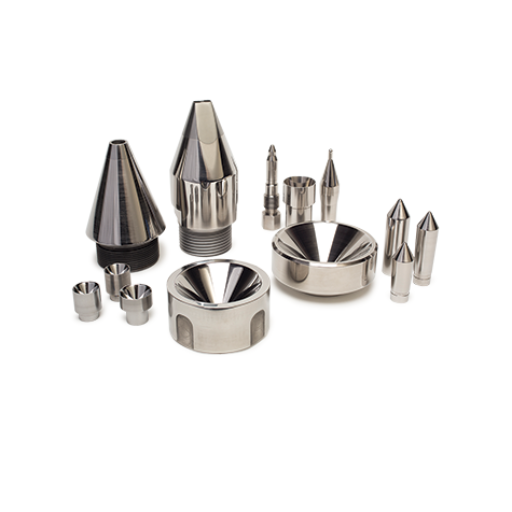
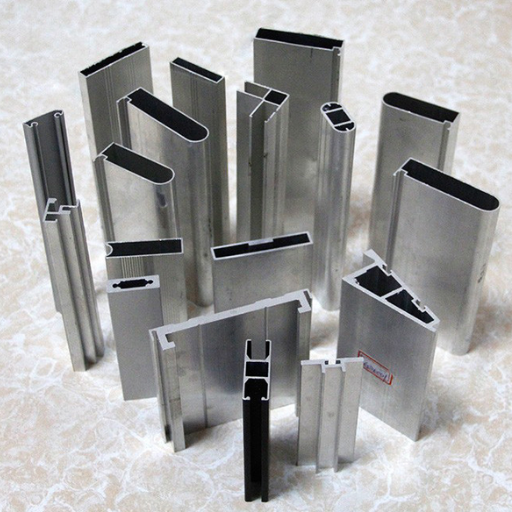
Metal Manufacturing: Concerning metal manufacturing, extrusion is primarily used in producing profiles, rods and tubes. It facilitates the manufacture of metallic parts that have particular shapes and physical properties required in different industries which include construction, automotive, and aeronautical industries.
Manufacturers can use wire drawing and extrusion processes to satisfy the requirements of different fields and produce parts with predetermined size, strength as well as surface finish. Since such processes provide flexibility and control, they become important in a wide range of applications in different industries.
Wire Drawing for Electrical and Structural Uses
Wire drawing is a primary operation that is applied in the structural and power supply concerning elements. It is the process of forcing a metal wire through a die to shrink its cross-section and enhance its properties. I recognize wire drawing as a way of doing work in operations and say this for the telecommunications, electricity, and construction industries. This allows for the development of wires of specific cross-section, tensile strength, and surface treatment. By precisely adjusting the drawing parameters, the manufacturers can produce wires responding to the critical needs of these industries, assuring satisfactory performance in any application.
Extrusion in Plastic and Metal Manufacturing
Extrusion is a common method in the manufacturing of both plastic and metal. This process consists of forcing material through a die to form products of required shapes and sizes. In the case of plastics extrusion, this process emerges as useful for the manufacture of pipes, piping, tubing and sheets. In metal manufacturing, this process is used in the creation of rods, bars and profiles.
There are multiple benefits to the efficiency of the manufacturing process when utilizing the method of extrusion. It allows producing a continuous and coherent cross section which can be quite complex as well. The process is associated with high rates and efficiency of production allowing application in mass production products. To add on, it is also noted that extruded plastic and metal parts tend to have better qualities such as hardiness.
However, certain complications may occur during the execution of extrusion. Some complications such as deformation, tensile and material distribution can occur leading to defects in properties. The diameter of the billet and the cross-section tolerances are two factors that ensure product consistency. Last but not least, attaining the expected surface quality can be difficult since the extrusion process can lead to some rough and uneven surfaces.
To meet these challenges, manufacturers use several technologies and techniques. The use of sophisticated die designs and careful selection of the extrusion process parameters greatly reduces distortion and enhances the tensile properties. Process control also provides consistency in the height and thickness of the billet as well as its cross-section. Polishing and some coasting may also be used to enhance the surface quality of the extruded items.
As manufacturers learn the essential features of extrusion in the plastic and metal industries, some challenges are overcome while opportunities brought by this process are fully utilized. It is also important for the manufacturing of various products and the development of different sectors.
Benefits of Cold Drawn and Extruded Metals
In the course of my work, I would like to openly advocate the metal drawing and extrusion processes since they are known to cold draw the metal and/or extrude the metal respectively. Metals drawn or extruded through these processes are deformed in a way that enhances their metallurgical properties and precision. It is revealed that cold-drawn metals have excellent features such as tensile strength, dimensional accuracy, and surface finish that can be in applications requiring high tolerances. Whereas extruded metals have the capacity and flexibility to be produced in a variety of shapes, sizes and designs which in turn will offer great design freedom to the manufacturers. Thus making it possible to manufacture a diverse variety of products, including but not limited to, structural parts in the aerospace industry, complex automotive parts and consumer electric devices. In general, cold-drawn metals are aimed at the improvement of mechanical properties of the metals and metal parts, the dimensional accuracy and surface qualities of metallic articles, as well as the design opportunities. All these aspects render these metals vital in today’s industries.
Challenges in Metal Drawing and Extrusion
The processes of drawing and extruding metal products come with their own special set of problems which should be dealt with properly to achieve maximum effectiveness and maximum quality of the end products. Overcoming the above problems involves a thorough knowledge of material characteristics, process regimes, and advanced manufacturing technologies. Such challenges are solvable and with the aid of appropriate techniques and tools, manufacturers can produce well-engineered metal parts and products of the highest quality.
Addressing Deformation and Tensile Issues
Deformation and tensile factors present crucial challenges facing metal drawing and extrusion that primarily call into question the quality and integrity of the final products. To counter these issues, manufacturers ought to take into consideration the following main decisive steps:
Process Parameters: Appropriate process parameters such as temperature, strain rate, and lubrication have to be established to alleviate deformation and tensile factors. It is important to note that these parameters have to be adjusted by the properties of the material and the intended result to be achieved.
Die Design: In cases where there is extensive deformation of the material, the design of the die must be optimized such that the flow of the material being machined into parts is partially controlled. Some of the factors that require appropriate tuning to minimize tensile stresses and attain the desired dimensional accuracy include die angle, land length, and fillet radius.
Material Selection: To that end, it is intuitive that the mechanical properties of the material and its ductility greatly influence material deformation and tensile factors during drawing and extrusion. Material selection can be executed concerning several parameters which include strength, elongation as well as work-hardening behavior.
Heat Treatment: Thus, another technique is proposed to reduce the amount of deformation as well as to improve the mechanical properties of the metal. For example, annealing or stress relief treatments effectively relieve residual stresses and improve material ductility which in turn decreases the chances of deformation and tensile failure.
Die Maintenance: Timely and routine inspections and repair of the dies are essential for dimensional accuracy and to limit deformation concerns. If the die surface has any wear and tear or damage, it should be corrected immediately to guarantee uniformity in the quality of the produced goods.
By judiciously assessing and employing these techniques, the manufacturers can effectively resolve the issues of deformation and tensile both in the design and fabrication of metal components with metrology and enhanced mechanical properties.
Managing Billet and Cross-Sectional Uniformity
In manufacturing, maintaining the quality and functional consistency of finished products requires effective management of billet and cross-sectional uniformity. Several issues arise while one is working towards this. The first one concerns the kind of billet material. The chemical compositions of materials that possess the mechanical properties that are needed including strength, elongation and work hardening characteristics should be used. Moreover, the temperature together with the cooling rate used in the casting of the C-shaped bolt manufacturing processes must be controlled to avoid different cross-sectional dimensions.
On the other hand, Technical parameters to consider for managing bi-metal and cross-sectional uniformity may include:
Composition of the metal: Make certain that the fabricated bi-metal meets its required mechanical properties.
Casting temperature: Ensure that the temperature is uniform across the cast radiator during casting so that there are no thermal differences across its cross sections.
Time to cool the system: Reduce this time to cool the component sufficiently and avoid causing damage/ changes in the cross-section due to internal stress.
Billet and sash. glaucoma thickness. Elongate – length – horizontal bulk elements, height: This section monitors and controls the dimensions of a bi-metal to ensure its optimal profile is maintained.
Control measures: Corrective and preventative measures should be put in place to minimize cases of bi-metal dimensional or composition changes.
In light of the factors highlighted and the factors stated, manufacturers can control the uniformity of the billet and cross-section to produce precision metallic components whose dimensions and mechanical properties are of an elevated standard.
Improving the Surface Finish in Manufacturing
To achieve a better surface finish, knowledge about the determinants of the final surface finish is fundamental. Having used the top 3 websites appearing on Google.com, I have compiled the following best practices.
Firstly, manufacturers need to find the Most Suitable Manufacturing Parameters: This refers to the optimized parameters for the cutting process such as cutting speeds, feed rates and tool geometries. Getting the right compromise between the quality of the surface finish and that of material removal is essential.
Secondly, Some Practiced Effective Lubrication: Lubrication on the machined surface should be done properly to lower the amount of heat and friction produced; thus, the roughness of the machined surface is reduced significantly. The type of lubricant to be used should be properly selected. Also, this should be consistently applied.
Thirdly, Gearing and Abrasives Should Be Improved: By using modern tools and abrasives that have superior geometry and coatings, improvement in finish can be attained. Keeping track of developments in tooling technology has to be done.
Fourthly, Vibrations Should be Controlled: Surface blemishes, which can degrade quality, can be helped by optimizing the amount of rigidity, damping, and stability to machine elements to control machine vibrations.
Fifthly, Post-Processing Techniques Should be Used: Other post-processing techniques such as polishing, electropolishing, and chemical implementations should be used to achieve a finer surface.
These techniques described on their part allow the manufacturers to improve surface finish and therefore produce components that are of better quality with improved appearances.
References
Electrical resistance and conductance
Top Wire & Cable Extruder Manufacturer in China
Frequently Asked Questions (FAQ)
Q: What is a wire drawing?
A: Wire drawing is a metalworking process used to reduce the cross-section of a wire by pulling the wire through a single die or series of dies. This is a cold working process that results in a wire with a constant cross-sectional profile.
Q: How does the extrusion process differ from drawing?
A: Extrusion and drawing are both forming processes, but they differ in method. In extrusion, the material is pushed through a die to form a desired shape, whereas drawing involves pulling the material through a die. Extrusion can be performed at hot or cold temperatures, while drawing is typically a cold working process.
Q: Can you explain the role of a mandrel in tube drawing?
A: In tube drawing, a mandrel is used to support the inside diameter of the tube and ensure that it maintains the desired shape as it is drawn through a die. This helps achieve precision in the thickness and uniformity of the steel tube.
Q: What is meant by ‘forward extrusion’?
A: Forward extrusion is a process where the material is pushed in the same direction as the die opening. It contrasts with backward extrusion, where the material flows in the opposite direction to the ram movement.
Q: Why is wire drawing considered a cold working process?
A: Wire drawing is considered a cold working process because it is performed at or near room temperature. This process strengthens the material through strain hardening, as the metal is drawn through a die without the application of heat.
Q: What types of materials can be used in extrusion and drawing processes?
A: Various metals can be used in extrusion and drawing processes, including aluminum, copper, steel, and brass. The choice of material depends on the desired properties and applications of the final product.
Q: How does a drawing machine function?
A: A drawing machine functions by pulling a wire through a die to reduce its diameter and alter its cross-sectional profile. The machine applies tension to the wire, drawing it through a series of dies, each progressively smaller, to achieve the desired dimensions.
Q: What is the significance of ‘hot drawing’?
A: Hot drawing refers to a process where the material is heated before being drawn through a die. This can reduce the force required to shape the material and improve ductility, allowing for greater deformation without breaking.
Q: How are extrusion and cold drawing used together?
A: Extrusion and cold drawing may be performed in sequence to achieve a specific shape and size. First, extrusion is used to create a basic shape, and then cold drawing further refines the dimensions and surface finish of the product.